Plasma cathode and protecting method thereof

A plasma and cathode technology, which is applied in the field of plasma technology and chemical synthesis, can solve the problems of low energy utilization rate and ablation, and achieve the effect of high energy utilization rate and improved stability

Active Publication Date: 2011-03-30
INST OF METAL RESEARCH - CHINESE ACAD OF SCI
View PDF0 Cites 2 Cited by
  • Summary
  • Abstract
  • Description
  • Claims
  • Application Information

AI Technical Summary

Problems solved by technology

[0005] The purpose of the present invention is to solve the problems of low energy utilization rate and severe ablation in the existing plasma cathode, and propose a new type of plasma cathode and protection method, so as to improve the life of the plasma cathode and the energy utilization rate of the cathode

Method used


Image

  • Plasma cathode and protecting method thereof
  • Plasma cathode and protecting method thereof
  • Plasma cathode and protecting method thereof

Examples


Embodiment 1

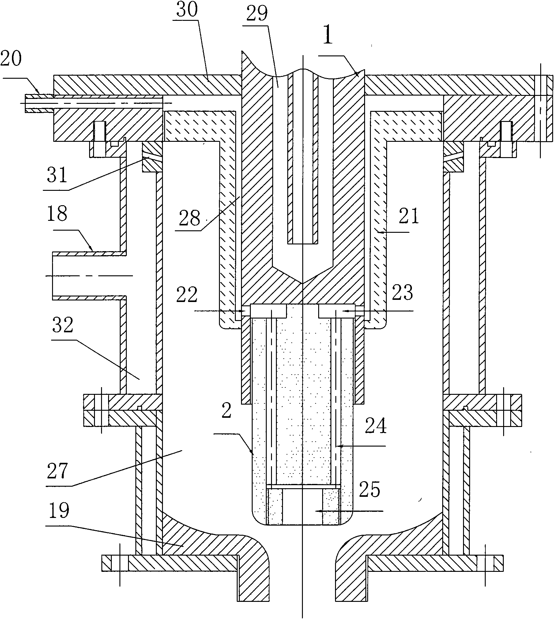
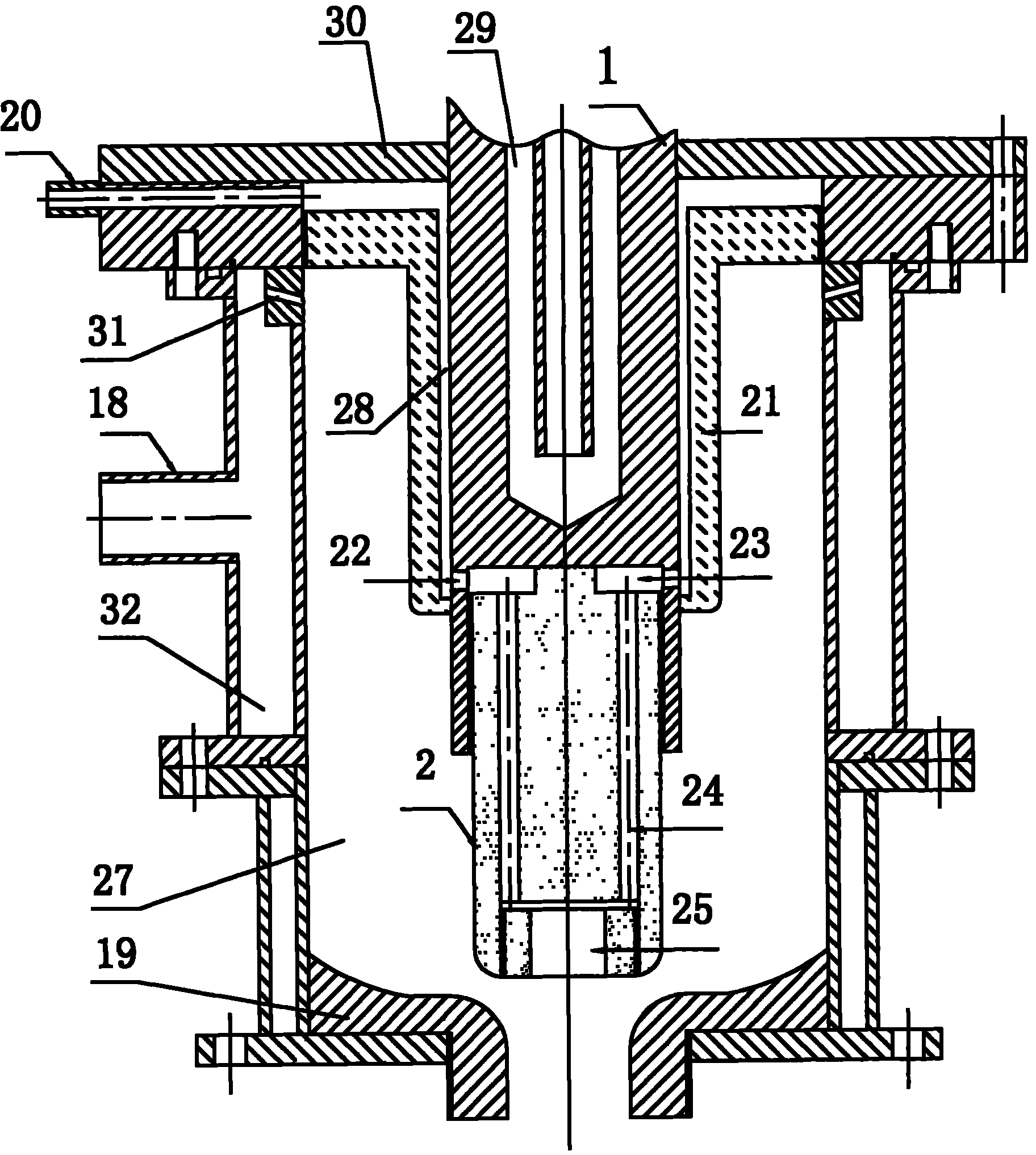
[0023] Such as figure 1 As shown, the plasma device is provided with an anode 19 and a cathode. The cathode extends into the anode cavity 27. The cathode is a water-cooled cathode (a cathode with a water-cooled channel 29) made of stainless steel 1 and a hollow cathode 2 made of graphite. It is connected to the cathode of the plasma device by screw thread. An insulating medium 21 is provided outside the water-cooled cathode 1 to separate the water-cooled cathode 1 from the anode cavity 27. A gap 28 is formed between the water-cooled cathode 1, the insulating medium 21 and the anode cover 30 outside the water-cooled cathode 1, and the inlet II20 communicates with the gap 28 . An annular gas cavity 32 is installed outside the anode cavity 27, and the outside of the annular gas cavity 32 is communicated with the inlet I 18, and a hole IV31 is opened on the inner wall of the annular gas cavity 32. The hollow cathode 2 is provided with an inner cavity 25 and a hole III24. One end o...

Embodiment 2

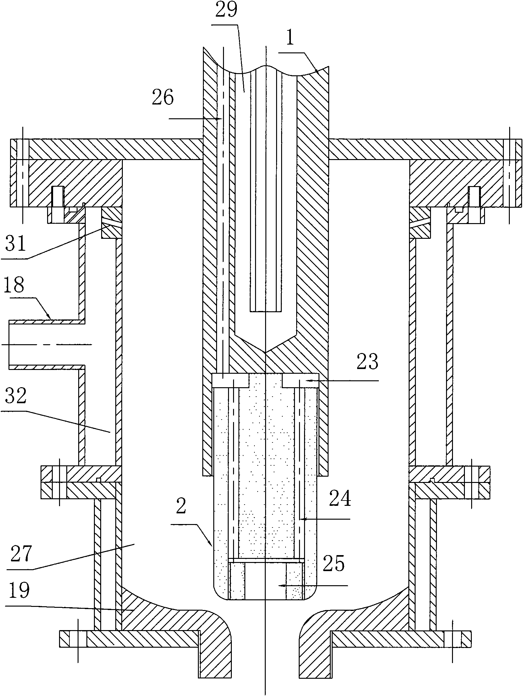
[0025] Such as figure 2 As shown, the plasma device is provided with an anode 19 and a cathode. The cathode extends into the anode cavity 27. The outside of the anode cavity 27 is equipped with an annular gas cavity 32. The outside of the annular gas cavity 32 is connected to the inlet I 18 and is on the inner wall of the annular gas cavity 32. There is a channel IV31. The cathode is a water-cooled cathode 1 made of stainless steel, and a hollow cathode 2 made of silicon carbide is screwed to form the cathode of the plasma device. An annular gas is opened between the water-cooled channel 29 of the water-cooled cathode 1 and the outer wall of the water-cooled cathode 1. In the channel 26, the hollow cathode 2 is provided with an inner cavity 25 and a hole III24. One end of the hole III24 is connected to the inner cavity 25, and the other end of the hole III24 communicates with the gas channel 26 through the hole II23. The protective gas passes through the gas channel 26 and th...


PUM


Abstract

The invention relates to the field of plasma technology and chemical synthesis, in particular to a direct-current plasma device cathode applied to plasma high-temperature synthesis and a protecting method thereof. The problems of low energy utilization rate and serious ablation of the traditional plasma cathode are solved. The plasma cathode is a composite cathode of a hollow cathode and a water cooling cathode, wherein one end of the composite cathode is the hollow cathode with a hollow structure while the other end is the water cooling cathode with a water cooling structure; gas passages communicated with each other are arranged on the hollow cathode and the water cooling cathode; one end of each gas passage is communicated with a gas inlet while the other end is communicated with the inner cavity of the hollow cathode; and mixed protective gas consisting of hydrogen and hydrocarbon is introduced into the hollow cathode from the gas passages. The technical scheme provided by the invention can greatly prolong the service life of the plasma cathode and improve the energy utilization rate of the cathode and has the characteristics of high working stability and wide application range.

Description

Technical field [0001] The invention relates to the fields of plasma technology and chemical synthesis, in particular to a direct current plasma device cathode and protection method used for plasma high-temperature synthesis. Background technique [0002] Due to its high energy density, high-energy electrons, ions and neutral particles, plasma is used in plasma chemical synthesis (such as plasma cracking natural gas to acetylene, plasma cracking hydrocarbon compounds to produce hydrogen and carbon black, plasma Cracking coal to produce acetylene, plasma lipid synthesis gas, etc.), and the treatment of toxic and hazardous wastes have broad application prospects. The low-voltage and high-current DC arc plasma technology commonly used in existing plasma devices. Due to the disadvantages of low power utilization and severe electrode ablation, this plasma is difficult to give full play to the application of plasma in the chemical synthesis field. The HUELS plant of International Spec...

Claims


Application Information

Patent Timeline
Patent Type & Authority Applications(China)
IPC IPC(8): H05H1/48
Inventor 杨永进张劲松孙家言孙博
Owner INST OF METAL RESEARCH - CHINESE ACAD OF SCI
Why Eureka
Try Eureka