Lime slurry jetting circulating fluid bed semi-dry process desulfurizer

A circulating fluidized bed, semi-dry desulfurization technology, applied in chemical instruments and methods, separation methods, dispersed particle separation, etc., can solve the problem of long time for material bed formation and stabilization process, slow system startup and adjustment response, dust removal and separation efficiency reduction and other problems, to achieve the effect of improving the desulfurization reaction efficiency, prolonging the contact reaction time, and reducing the workload

Active Publication Date: 2011-04-06
CISDI ENG CO LTD
View PDF4 Cites 4 Cited by
  • Summary
  • Abstract
  • Description
  • Claims
  • Application Information

AI Technical Summary

Problems solved by technology

[0004] In the prior art, the circulating fluidized bed semi-dry desulfurization device has the following problems: 1. The gas-solid separator is connected to the reaction tower through pipelines or directly connected, and the flue gas and materials at the outlet of the reaction tower directly enter the gas-solid separator. When the amount of flue gas increases, the gas-solid separator operates at a high load, and the efficiency of dust removal and separation decreases; when the amount of desulfurized flue gas decreases, the efficiency in the reaction tower is low due to insufficient turbulence and disturbance; The semi-dry desulfurization device has poor adaptability to the working conditions of sintering flue gas and other flue gas fluctuations or frequent fluctuations
2. When the circulating fluidized bed is started, the starting material enters the reaction tower through the nozzle of the feeding system, and the formation and stabilization of the material bed takes a long time, resulting in slow system startup and adjustment response

Method used


Image

  • Lime slurry jetting circulating fluid bed semi-dry process desulfurizer
  • Lime slurry jetting circulating fluid bed semi-dry process desulfurizer
  • Lime slurry jetting circulating fluid bed semi-dry process desulfurizer

Examples


Embodiment Construction

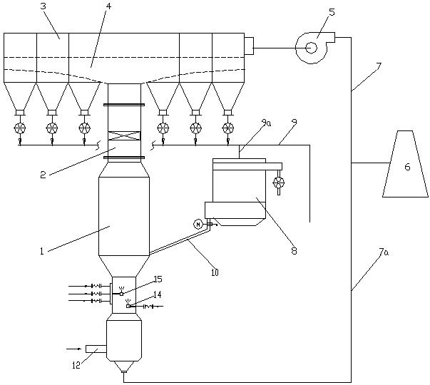
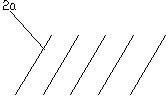
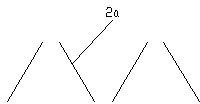
[0019] figure 1 It is a schematic flow chart of the present invention, figure 2 It is a schematic diagram of one of the arrangements of spoiler baffles, as shown in the figure: the semi-dry desulfurization device of the sprayed lime slurry circulating fluidized bed in this embodiment includes desulfurization reaction towers 1, gas-solid separation device 3 and induced draft fan 5, the lime slurry nozzle 15 and flue gas inlet 12 at the lower part of the desulfurization reaction tower 1, the upper part of the desulfurization reaction tower 1 is provided with a post-reaction gas outlet, and the post-reaction gas outlet of the desulfurization reaction tower 1 is separated from gas-solid The devices 3 communicate with each other through the spoiler 2, and the spoiler 2 is located at the upper part of the post-reaction gas outlet of the desulfurization reaction tower 1.

[0020] In this embodiment, the gas-solid separator 3 is a bag filter group located on the upper part of the sp...


PUM


Abstract

The invention discloses a lime slurry jetting circulating fluid bed semi-dry process desulfurizer which comprises a desulfurization reaction column, a gas-solid separator and a draught fan, wherein the lower part of the desulfurization reaction column is provided with a lime slurry nozzle and a fume inlet; an after-reaction gas outlet of the desulfurization reaction column is communicated with the gas-solid separator through a spoiler; and the spoiler is positioned on the upper part of the after-reaction gas outlet of the desulfurization reaction column. In the invention, the upper part of the gas outlet of the desulfurization reaction column is provided with the spoiler which can forcibly mix the gas-solid mixture discharged by the desulfurization reaction into a turbulent condition, thereby strengthening the desulfurization reaction of the mixture; and meanwhile, part of unreacted slurry particles return to the desulfurization reaction column for reaction after colliding with each other in the spoiler, thereby enhancing the desulfurization efficiency. The desulfurizer can reduce the working load of the gas-solid separator under the condition of high fume flow on the premise of ensuring the separating effect, and is applicable to high-flow fume desulfurization. When the fume flow is low, the turbulence is strengthened by the spoiler, thereby prolonging the contact reaction time and enhancing the desulfurization efficiency.

Description

technical field [0001] The invention relates to an environmental protection device for flue gas treatment, in particular to a device for desulfurizing flue gas. Background technique [0002] Semi-dry desulfurization technology is to spray lime slurry droplets into the desulfurization reaction tower, the droplets react with sulfur dioxide in the flue gas to form calcium sulfite and calcium sulfate, and, through the action of high-temperature flue gas, the water in the lime slurry evaporates, A dry product was obtained. [0003] The specific process of the circulating fluidized bed semi-dry flue gas desulfurization technology is that the sulfur-containing flue gas enters the reaction tower from the bottom of the circulating fluidized bed, is accelerated in the Venturi section of the reaction tower, and sprays the sulfur-containing flue gas into the tower from the side wall of the reaction tower. Blow up with lime slurry and circulating reflux material to form a boiling bed. ...

Claims


Application Information

Patent Timeline
Patent Type & Authority Applications(China)
IPC IPC(8): B01D53/80B01D53/50
Inventor 王珂刘旭陈继辉丹宇姚波
Owner CISDI ENG CO LTD
Why Eureka
Try Eureka