Photon sieve phase contrast objective lens, manufacturing method and imaging method

A manufacturing method and photon sieve technology, applied in the field of objective lenses, can solve the problems of blurred image details, difficult precise alignment, and low image contrast, and achieve the effects of high imaging resolution and imaging contrast, precise alignment, and simple system structure

Active Publication Date: 2011-04-06
HUAWEI TEHCHNOLOGIES CO LTD
View PDF3 Cites 9 Cited by
  • Summary
  • Abstract
  • Description
  • Claims
  • Application Information

AI Technical Summary

Problems solved by technology

However, the image details are blurred, the image contrast is low, and the zone plate is difficult to precisely align with the phase contrast ring on its focal plane

Method used


Image

  • Photon sieve phase contrast objective lens, manufacturing method and imaging method
  • Photon sieve phase contrast objective lens, manufacturing method and imaging method
  • Photon sieve phase contrast objective lens, manufacturing method and imaging method

Examples


Embodiment Construction

[0035] The above-mentioned photon sieve phase contrast objective lens will be further described below mainly in conjunction with the accompanying drawings and specific embodiments.

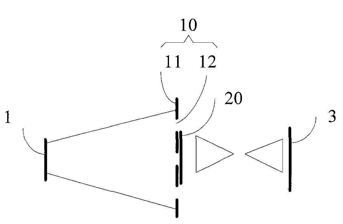
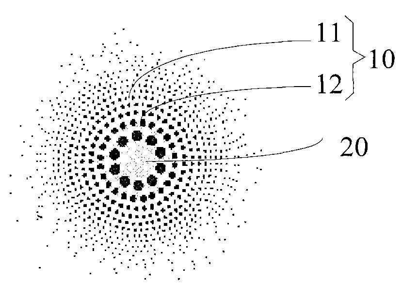
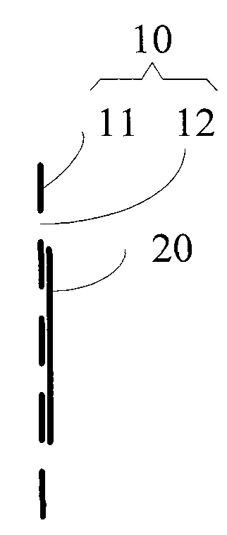
[0036] figure 1 Schematic diagram of photon sieve phase-contrast microscopy. In one embodiment, the photon sieve phase contrast objective lens includes a photon sieve lens 10 and a phase changing plate 20 disposed on the surface of the photon sieve lens 10 . The photon sieve lens 10 is formed by a base 11 and a plurality of light-transmitting holes 12 disposed on the base 11 . The phase changing plate 20 is located in the middle of the photon sieve lens 10 or surrounds the edge of the photon sieve lens 10 , and the center of the phase changing plate 20 and the center of the photon sieve lens 10 are on the same axis. In this way, the phase changing plate 20 and the photon sieve lens 10 are closely combined. A part of the light irradiated on the object to be tested forms off-axis diffracted light...


PUM


Abstract

The invention relates to a photon sieve phase contrast objective lens which comprises a photon sieve lens formed by a substrate and a plurality of light-transmitting holes arranged on the substrate, and a phase-changing plate arranged on the surface of the photon sieve lens, wherein the phase-changing plate is positioned at the middle part of the photon sieve lens or on the edge around the photon sieve lens, and the center of the photon sieve lens and the center of the phase-changing plate are positioned on the same axial line. In addition, the invention further provides a manufacturing method of the photon sieve phase contrast objective lens and an imaging method. In the photon sieve phase contrast objective lens, the manufacturing method and the imaging method, the photon sieve lens is adopted for suppressing side lobe and high-order diffraction focus, thereby realizing high imaging resolution and high imaging contrast; and the photon sieve lens and the phase-changing plate are etched on the same substrate, the phase-changing plate is arranged on the surface of the photon sieve lens, and the center of the photon sieve lens and the center of the phase-changing plate are positioned on the same axial line, thereby being capable of realizing precise alignment, simultaneously reducing exposure time and exposure dose and being capable of realizing non-destructive detection with high imaging resolution and high imaging contrast of a minute structure in a weakly absorbing material.

Description

【Technical field】 [0001] The invention relates to the field of objective lenses, in particular to a photon sieve phase contrast objective lens, a manufacturing method and an imaging method. 【Background technique】 [0002] Short-wave electromagnetic radiation has a strong ability to penetrate objects. Short-wave electromagnetic radiation imaging technology is widely used in non-destructive testing of internal structures of objects in clinical medicine, scientific research and industrial fields. Because of the difference in lightness and darkness between different areas on the image, that is, contrast, it is possible to observe clear image details. A short-wave microscope is a device that uses short-wave electromagnetic radiation such as ultraviolet or X-rays to obtain a magnified image of the object under test. The image contrast obtained by the microscope usually depends on the energy absorption or phase modulation of the photoelectron radiation by the measured object. Th...

Claims


Application Information

Patent Timeline
IPC IPC(8): G02B5/18G02B27/42G21K7/00
Inventor 程冠晓胡超
Owner HUAWEI TEHCHNOLOGIES CO LTD
Why Eureka
Try Eureka