Four-slider zoom compensation mechanism of zoom lens

A technology of zooming and sliding rods, applied in installation, optics, instruments, etc., can solve the problems of optical structure design limitations, inability to design zoom and compensation structures, etc., and achieve the effect of reducing processing difficulty

Inactive Publication Date: 2011-04-06
CHANGCHUN INST OF OPTICS FINE MECHANICS & PHYSICS CHINESE ACAD OF SCI
View PDF5 Cites 14 Cited by
  • Summary
  • Abstract
  • Description
  • Claims
  • Application Information

AI Technical Summary

Problems solved by technology

[0006] When the cam 8 rotates with the cam shaft system, the cam curve on the cam 8 drives the zoom lens group 22 and the compensation lens group 18 to move linearly along the first slide bar 7 and the anti-rotation slide bar 25 respectively, and the zoom lens group 22 and the compensation lens group The relative position of the lens group 18 is determined by the cam curve on the cam 8, and the mutual angular relationship is determined by the mutual position and deformation of the first sliding bar 7 and the anti-rotation sliding bar 25. This mutual angular relationship directly determines The imaging quality of zoom TV, the first slide bar 7 and anti-rotation slide bar 25 are fixed in the end hole of lens barrel 13, so the end of lens barrel 13 is installed the hole of first slide bar 7 and anti-rotation slide bar 25 The machining accuracy is very important. The machining position accuracy is limited by the processing machine tool, so that the mutual position accuracy of the first slide bar 7 and the anti-rotation slide bar 25 will not be too high. Slide bar 7 and anti-rotation slide bar 25 bear, and the second slide bar 17 only plays the effect of restricting rotation, does not bear weight, when variable power mirror group 22 and compensating mirror group 18 dimensions are bigger, weight is just heavier, like this by a single When the slider is supported, the deformation of the slider will be large. When the focal length of the zoom TV changes, the error of the relative change between the zoom lens group and the compensation lens group in the center of the movement will be large. In order to ensure that the image is clear when the zoom TV is zoomed, this In such a structure supported by a single rod, the weight of the zoom lens group and the compensation lens group cannot be too large, which limits the design of the optical structure, and cannot design a large-caliber zoom and compensation structure

Method used


Image

  • Four-slider zoom compensation mechanism of zoom lens
  • Four-slider zoom compensation mechanism of zoom lens
  • Four-slider zoom compensation mechanism of zoom lens

Examples


Embodiment Construction

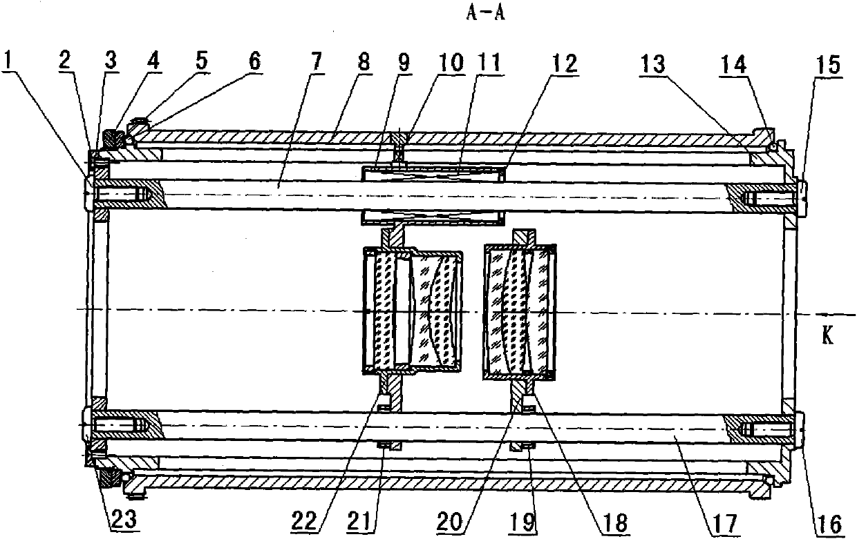
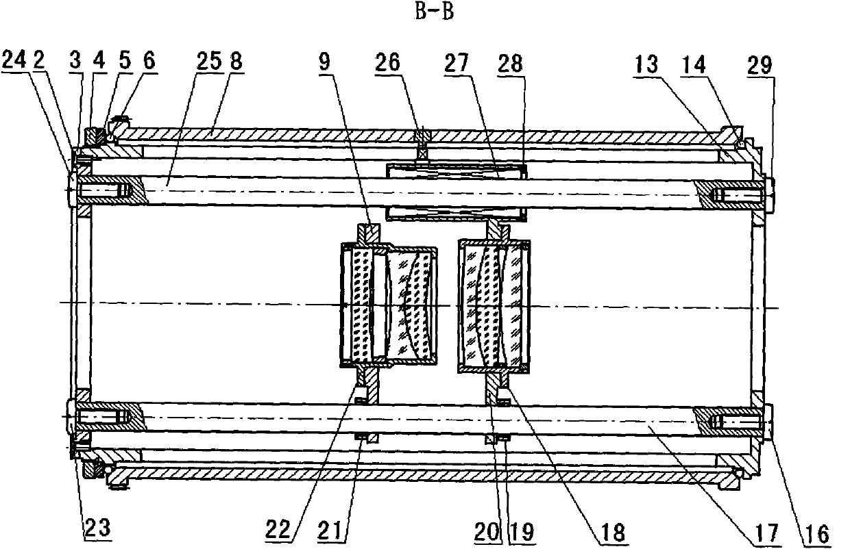
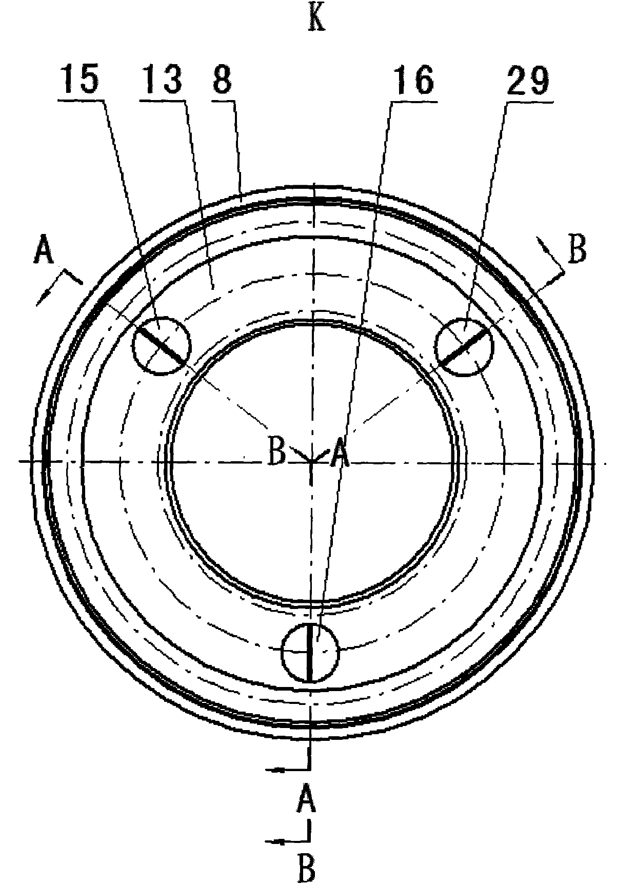
[0020] The invention according to Figure 4 , Figure 5 , Figure 6The structure shown is implemented. Wherein the left bearing stop ring 35, the first steel ball 36, the first slide bar 37, the cam 38, the lens barrel 43, the second steel ball 44, the second slide bar 49, the third slide bar 50, and the fourth slide bar 60 adopt GCr15 steel material; the first slider left screw 30, the first washer 31, the first screw 32, the cover plate 33, the left adjustment nut 34, the left bearing stop ring 35, the zoom carriage 39, the zoom guide shaft 40, the first A zoom bearing pressure ring 42, a second washer 45, a right screw 46 of the first slide bar, a right screw 47 of a second slide bar, a right screw 48 of a third slide bar, a compensation carriage 52, a second zoom bearing press ring 53 , The third slide bar left screw 56, the second slide bar left screw 57, the fourth slide bar left screw 58, the third washer 59, the compensation guide shaft 61, the first compensation be...


PUM


Abstract

The invention discloses a four-slider zoom compensation mechanism of a zoom lens and relates to a zoom compensation mechanism, which belongs to the technical field of photoelectric instruments. The technical problem to be solved is to provide the four-slider zoom compensation mechanism of the zoom lens. The technical scheme is that the four-slider zoom compensation mechanism of the zoom lens comprises the following parts: a cover plate, a left adjusting nut, a left bearing retainer ring, a first steel ball, a first slider, a cam, a zoom carriage, a zoom guide shaft, a lens cone, a second steel ball, a second slider, a third slider, a compensation lens set, a compensation carriage, a zoom lens set, a fourth slider, a compensation guide shaft and the like. When the cam rotates, the zoom guide shaft performs curvilinear motion along a cam groove to drive the zoom lens set to move axially along the first slider and the second slider; meanwhile, the compensation guide shaft performs the curvilinear motion along the cam groove to drive the compensation lens set to move axially along the second slider and the forth slider, so that the focus distance regulation of a large-aperture zoom lens is realized, and regulation precision is high.

Description

technical field [0001] The invention belongs to the technical field of photoelectric instruments and relates to a four-slide-bar variable magnification compensation mechanism for a zoom lens. Background technique [0002] Most of the optoelectronic instruments used for observation, recording, tracking, and testing use optical zoom lenses, and the imaging quality of optical lenses with variable focal length is determined by its zoom compensation mechanism. [0003] The prior art closest to the present invention is the "three-bar variable power compensation mechanism for the zoom lens" developed by the Changchun Institute of Optics, Fine Mechanics and Physics, Chinese Academy of Sciences. Such as figure 1 , figure 2 , image 3 shown. Including the first slider left screw 1, screw 2, cover plate 3, left adjustment nut 4, left bearing stop ring 5, first steel ball 6, first slider 7, cam 8, zoom slider 9, zoom Guide shaft 10, first zoom linear bearing 11, first zoom bearing...

Claims


Application Information

Patent Timeline
Patent Type & Authority Applications(China)
IPC IPC(8): G02B7/10G02B7/09
Inventor 于萍韩光宇
Owner CHANGCHUN INST OF OPTICS FINE MECHANICS & PHYSICS CHINESE ACAD OF SCI
Why Eureka
Try Eureka