Optical structure of LED liquid crystal projector with single polarization converter

A polarization converter and optical structure technology, applied in optics, optical components, instruments, etc., can solve problems such as difficult to borrow, micro projectors that have not been seen, and large LED light-emitting area, so as to achieve simple processing and assembly, and improve Effect of light energy utilization efficiency and brightness, small size

Inactive Publication Date: 2011-04-06
ZHEJIANG JINCHENG SCI & TECH
View PDF5 Cites 8 Cited by
  • Summary
  • Abstract
  • Description
  • Claims
  • Application Information

AI Technical Summary

Problems solved by technology

In addition, due to the large light-emitting area of ​​LEDs, it is difficult to borrow mature PCS technology
So far, there has not been a product of a miniature projector applying polarization conversion technology

Method used


Image

  • Optical structure of LED liquid crystal projector with single polarization converter
  • Optical structure of LED liquid crystal projector with single polarization converter
  • Optical structure of LED liquid crystal projector with single polarization converter

Examples


Embodiment Construction

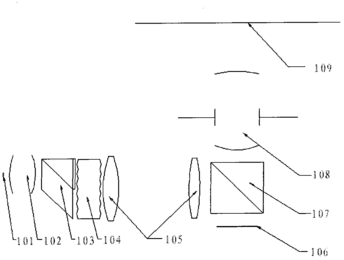
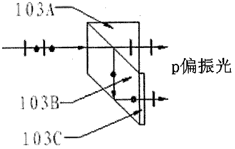
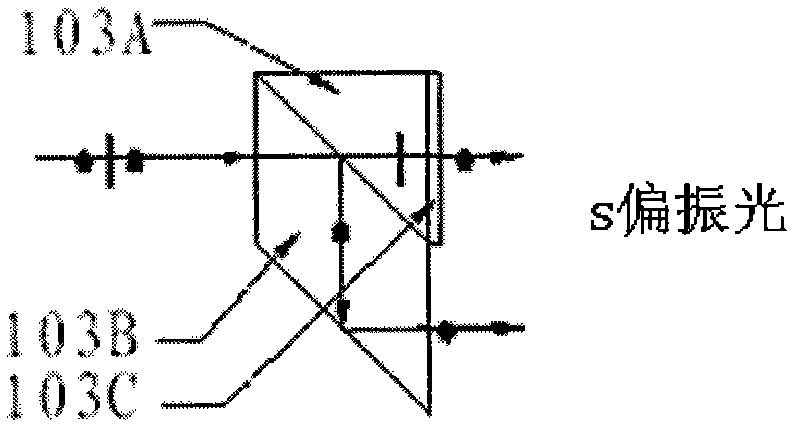
[0022] refer to figure 1 , the optical structure of the LED liquid crystal projector with a single polarization converter in Scheme 1, including the illumination optical axis and the imaging optical axis, and the light source LED 101, the collimating mirror 102, and the single transmissive polarization converter 103 are placed in sequence on the illumination optical axis , lens array 104 and relay optical group 105, place LCOS liquid crystal screen 106, PBS (polarizing beam splitter) 107 and projection lens 108 successively on the imaging optical axis, the illumination optical axis is perpendicular to imaging optical axis; After the light is collimated by the collimating mirror 102, it enters a single transmissive polarization converter 103, and the unpolarized light is converted into polarized light by the single transmissive polarization converter 103, and then enters the lens array 104, and the beam is shaped by the lens array 104 Afterwards, the relay light group 105 reach...


PUM


Abstract

The invention provides an optical structure of an LED liquid crystal projector with a single polarization converter, comprising a lighting optical shaft and an imaging optical shaft which are vertical, wherein an LED, a collimating lens, a single transmission polarization converter, a lens array and a repeater light set are orderly arranged on the lighting optical shaft; an LCOS liquid crystal display, a PBS and a projection lens are orderly located on the imaging optical shaft; or the optical structure of the LED liquid crystal projector with the single polarization converter comprises two lighting optical shafts and an imaging optical shaft; the LED, the collimating lens and the single transmission polarization converter are orderly located on a first lighting optical shaft; the lens array and the repeater light set are orderly arranged on a second lighting optical shaft; the LCOS liquid crystal display, the PBS and the projection lens are orderly located on the imaging optical shaft; the first lighting optical shaft is parallel to the imaging optical shaft; and the first lighting optical shaft and the imaging optical shaft are both vertical to the second lighting optical shaft. The optical structure can convert the polarization light via the single transmission polarization converter or the single reflection polarization converter; and the optical structure is small in volume, high in light efficiency, low in cost and simple in machining and assembling.

Description

technical field [0001] The invention relates to the optical structure of an LED liquid crystal projector, especially the optical structure of an LED liquid crystal projector with a single polarization converter. Background technique [0002] Liquid crystal projectors are widely used photoelectric products. At present, common liquid crystal projectors use metal halide tungsten lamps as light sources. Although they have high brightness, they are bulky. This type of liquid crystal projector usually uses a polarization conversion system (PCS) to convert the non-polarized light of the metal halide tungsten lamp into polarized light to improve the utilization rate of light energy. A PCS usually includes a row of cubic prism arrays and a double row of lens arrays. The cubic prism array is bonded together by n cubic prisms, because after unpolarized light passes through the cubic prisms, the diameter of the outgoing beam will increase to (n+1) / n times the diameter of the incident b...

Claims


Application Information

Patent Timeline
IPC IPC(8): G02B27/18G02B27/28G03B21/20
CPCG03B21/14G02B27/283H04N9/3197H04N9/3167G03B21/2033G03B21/2073
Inventor 陆祖康吴碧珍田宝龙倪旭翔
Owner ZHEJIANG JINCHENG SCI & TECH
Why Eureka
Try Eureka