Light-emitting component and manufacturing method thereof
A technology for light-emitting elements and light-emitting glass, applied in electrical components, semiconductor devices, circuits, etc., can solve the problems of low luminous efficiency, reducing the luminous efficiency of field emission devices, and limiting the application of field emission devices.
- Summary
- Abstract
- Description
- Claims
- Application Information
AI Technical Summary
Problems solved by technology
Method used
Image

Examples
preparation example Construction
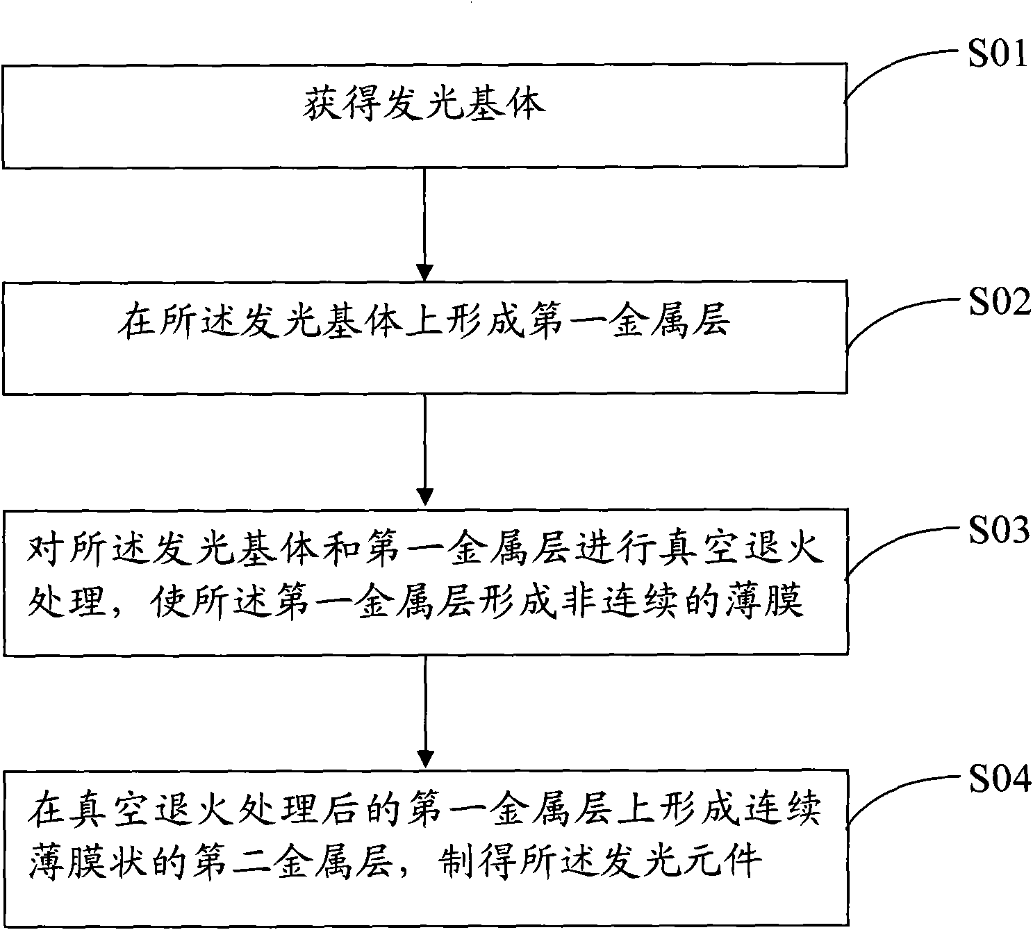
[0025] please combine figure 1 see figure 2 , the light-emitting element preparation method of the embodiment of the present invention is described, and the preparation method includes the following steps:
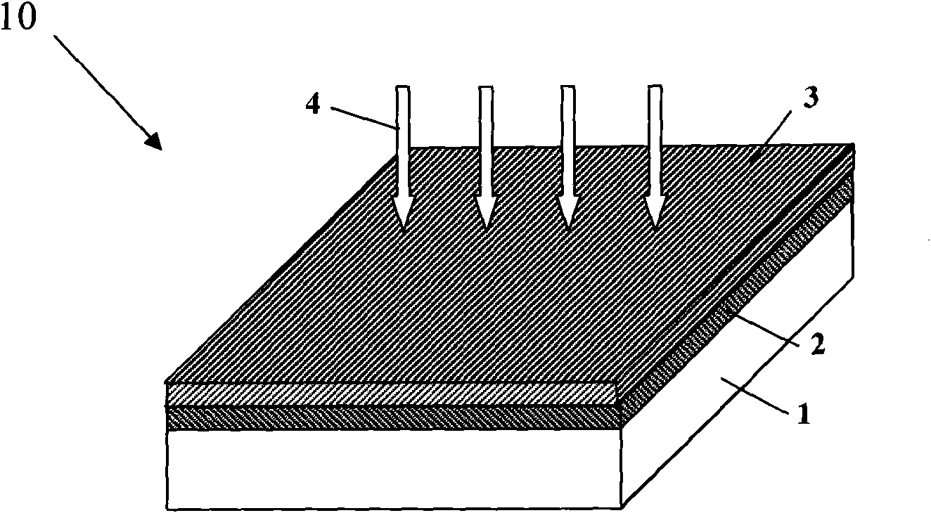
[0026] S01: obtain light-emitting substrate 1;
[0027] S02: forming a first metal layer 2 on the light-emitting substrate 1;
[0028] S03: vacuum annealing the light-emitting substrate 1 and the first metal layer 2 to form a discontinuous film on the first metal layer; and
[0029] S04 : forming the second metal layer 3 in the form of a continuous thin film on the first metal layer 2 after the vacuum annealing treatment to prepare the light-emitting element 10 .
[0030] The light-emitting substrate 1 in step S01 may directly use an existing light-emitting substrate, or prepare a light-emitting substrate, including but not limited to the above-mentioned light-emitting glass layer, rare-earth-doped light-emitting glass layer, or light-emitting composite layer.
[0031] ...
Embodiment 1
[0036] The light-emitting element structure of the present embodiment 1 is basically as follows: figure 1 As shown, the specific preparation method is as follows: select the size as 1×1cm 2 , surface polished Li 3 YSi 3 o 9 : Tb luminescent glass (that is, the first light-emitting element as a comparison), using magnetron sputtering equipment to deposit a silver film with a thickness of 2nm on its surface, and then place it at an air pressure less than 1×10 -3 Under a vacuum environment of Pa, heat treatment at 200° C. for half an hour, and naturally cool to room temperature to obtain a glass light-emitting element with the first metal layer, which is the second light-emitting element for comparison. Then, a 20nm thick aluminum film was deposited on the surface of the first metal layer formed on the luminescent glass by magnetron sputtering equipment, and the glass light-emitting element with the first metal layer and the second metal layer in Example 1 was obtained. . In...
Embodiment 2
[0038] The light-emitting element structure of the present embodiment 2 is basically as follows figure 1 As shown, the specific preparation method is as follows: select the size as 1×1cm 2 , surface polished Li 3 YSi 3 o 9 : Tb luminescent glass (that is, the first light-emitting element as a comparison), using magnetron sputtering equipment to deposit a silver film with a thickness of 2nm on its surface, and then place it at an air pressure less than 1×10 -3 Under a vacuum environment of Pa, heat treatment at 200° C. for half an hour, and naturally cool to room temperature to obtain a glass light-emitting element with the first metal layer, which is the second light-emitting element for comparison. Then, a 50nm-thick aluminum film was deposited on the surface of the first metal layer formed on the luminescent glass by magnetron sputtering equipment to obtain the light-emitting element with the first metal layer and the second metal layer in Example 2. The silver film afte...
PUM
| Property | Measurement | Unit |
|---|---|---|
| thickness | aaaaa | aaaaa |
| thickness | aaaaa | aaaaa |
| thickness | aaaaa | aaaaa |
Abstract
Description
Claims
Application Information
 - R&D
- Intellectual Property
- Life Sciences
- Materials
- Tech Scout
- Unparalleled Data Quality
- Higher Quality Content
- 60% Fewer Hallucinations
Browse by: Latest US Patents, China's latest patents, Technical Efficacy Thesaurus, Application Domain, Technology Topic, Popular Technical Reports.
© 2025 PatSnap. All rights reserved.Legal|Privacy policy|Modern Slavery Act Transparency Statement|Sitemap|About US| Contact US: help@patsnap.com