Rotor manufacture process

A manufacturing process and rotor technology, applied in the manufacture of stator/rotor body, etc., can solve problems such as unstable product quality, excessive energy consumption, and low efficiency, and achieve stable and reliable product quality, increased production efficiency, and reduced costs.

Inactive Publication Date: 2011-04-06
镇江中虎弹簧有限公司
View PDF4 Cites 20 Cited by
  • Summary
  • Abstract
  • Description
  • Claims
  • Application Information

AI Technical Summary

Problems solved by technology

Traditional processing methods have defects such as low efficiency, excessive energy consumption, excessive investment in equipment, and unstable product quality.
The rotor is a kind of transmission mechanism, which has high requirements on the strength of the epicycloid. At the same time, the metallographic requirements of the product are extremely high (the grain size grade is above 6), which is difficult to achieve by traditional manufacturing methods.
Traditional process route: blanking→drilling→turning end face boring 1→turning end face 2→pull spline→milling epicycloid; this production method is inefficient, only about 80 pieces of blanks can be produced per shift, and the investment in equipment and tools Too large, in addition, the waste of raw materials is serious (the average waste of a single blank is about 0.6Kg), and the defects of the hot-rolled bar itself (such as inclusions, metal fibers are not smooth, etc.) cannot be compensated by subsequent processing, which brings hidden dangers to product quality

Method used


Image

  • Rotor manufacture process
  • Rotor manufacture process

Examples


Embodiment Construction

[0030] The present invention will be further described in detail below with reference to the drawings and specific embodiments.

[0031] The process route of the present invention is: blanking → annealing → billet making → lubrication → pre-forming → forming extrusion;

[0032] The first step: blanking, using CNC band sawing machine blanking, verticality ≤0.5;

[0033] The second step: Annealing, using a well-type vacuum annealing furnace to vacuum and fill with nitrogen protection annealing, after annealing, oxidation and decarburization unilateral ≤0.1, the material hardness after annealing HB113-120;

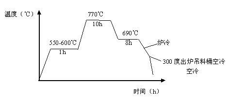
[0034] 20CrMnTi spheroidizing annealing process:

[0035] Such as figure 1 As shown, the annealing process is as follows: Put the blanks into the annealing furnace and cover the furnace cover, first raise the furnace temperature to 550-600 degrees for 1H, then increase the temperature to 770 degrees for 10 hours, and then slowly After cooling to 690°C and holding for 8H, turn ...


PUM

PropertyMeasurementUnit
hardnessaaaaaaaaaa
hardnessaaaaaaaaaa

Abstract

The invention relates to a rotor manufacture process comprising the following process lines: (1) blanking: blanking by adopting a numerical control band sawing machine with the verticality of not larger than 0.5; (2) annealing: vacuumizing by adopting a well-type vacuum annealing furnace and inflating nitrogen to protect annealing, wherein the annealed oxidized and decarburized single edge is not larger than 0.1, and the annealed material hardness HB is 113-120; (3) making a blank: making a blank by adopting a digital control lathe of CK6130, wherein the height error is controlled within 0.5; (4) carrying out the lubricating process as follows; (5) preforming: extruding by adopting a hydraulic press of 2000kN with the extrusion force P of 90 T, wherein the dimension accuracy is -0.05 to 0.05 and the surface roughness is 3.2; and (6) forming and extruding: extruding by adopting the hydraulic press of 2,000kN with the extrusion force P of 80 T, the cycloid accuracy of -0.05 to 0.05 and the extrusion velocity of not smaller than 4 pieces per min, wherein the extrusion length is 150 mm, the surface roughness is 1.6, and the extruded hardness HB is 200-210.

Description

Technical field [0001] The invention relates to a new manufacturing process of a rotor, which is used in the field of hydraulic transmission and belongs to the technical field of hydraulic motors. Background technique [0002] At present, there are many types of rotors on the market, which are widely used in hydraulic motors and steering gears, but they are basically processed by traditional manufacturing techniques. Traditional processing methods have defects such as low efficiency, excessive energy consumption, excessive investment in equipment, and unstable product quality. The rotor is a kind of transmission mechanism, which has high requirements on the strength of the outer cycloid. At the same time, the metallographic requirements of the product are extremely high (grain size grade is above 6), which is difficult to achieve with traditional manufacturing methods. The traditional process route: blanking→drilling→boring 1→car end 2→spline→milling epicycloid; this production ...

Claims


Application Information

Patent Timeline
Patent Type & Authority Applications(China)
IPC IPC(8): H02K15/02
Inventor 孟昭达
Owner 镇江中虎弹簧有限公司
Why Eureka
Try Eureka