H-bridge driving control circuit of motor

A technology of drive control circuit and drive unit, which is applied in the direction of starter, excitation or armature current control, motor generator/starter, etc. of a single DC motor, and can solve the problem of no anti-interference measures, weak anti-electromagnetic interference, Field effect tube misconduct and other problems, to improve the anti-interference ability, ensure reliable work, and easy to implement

Inactive Publication Date: 2011-04-06
SUZHOU R&D CENT OF NO 214 RES INST OF CHINA NORTH IND GRP
View PDF9 Cites 21 Cited by
  • Summary
  • Abstract
  • Description
  • Claims
  • Application Information

AI Technical Summary

Problems solved by technology

The disadvantages of this circuit are: first, the ability to resist electromagnetic interference is weak; second, when the motor is started, it is easy to cause interference to the control signal, resulting in false conduction of the field effect tube;

Method used


Image

  • H-bridge driving control circuit of motor
  • H-bridge driving control circuit of motor
  • H-bridge driving control circuit of motor

Examples


Embodiment Construction

[0026] Below in conjunction with accompanying drawing, preferred specific embodiment of the present invention is described:

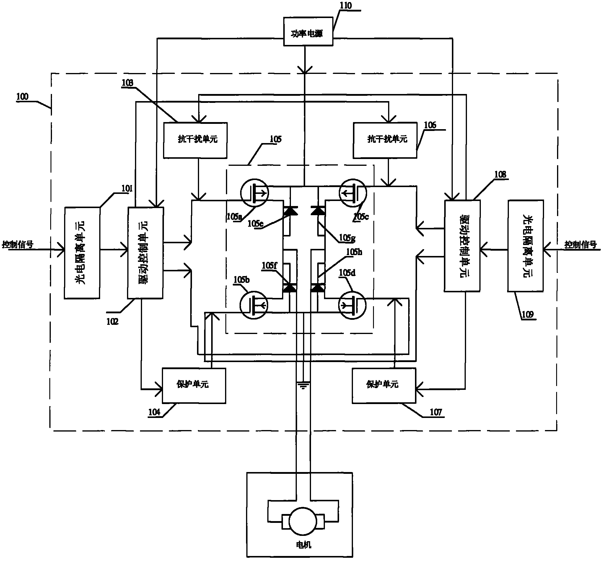
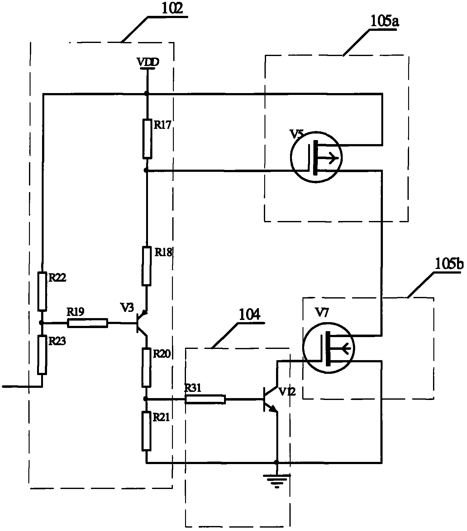
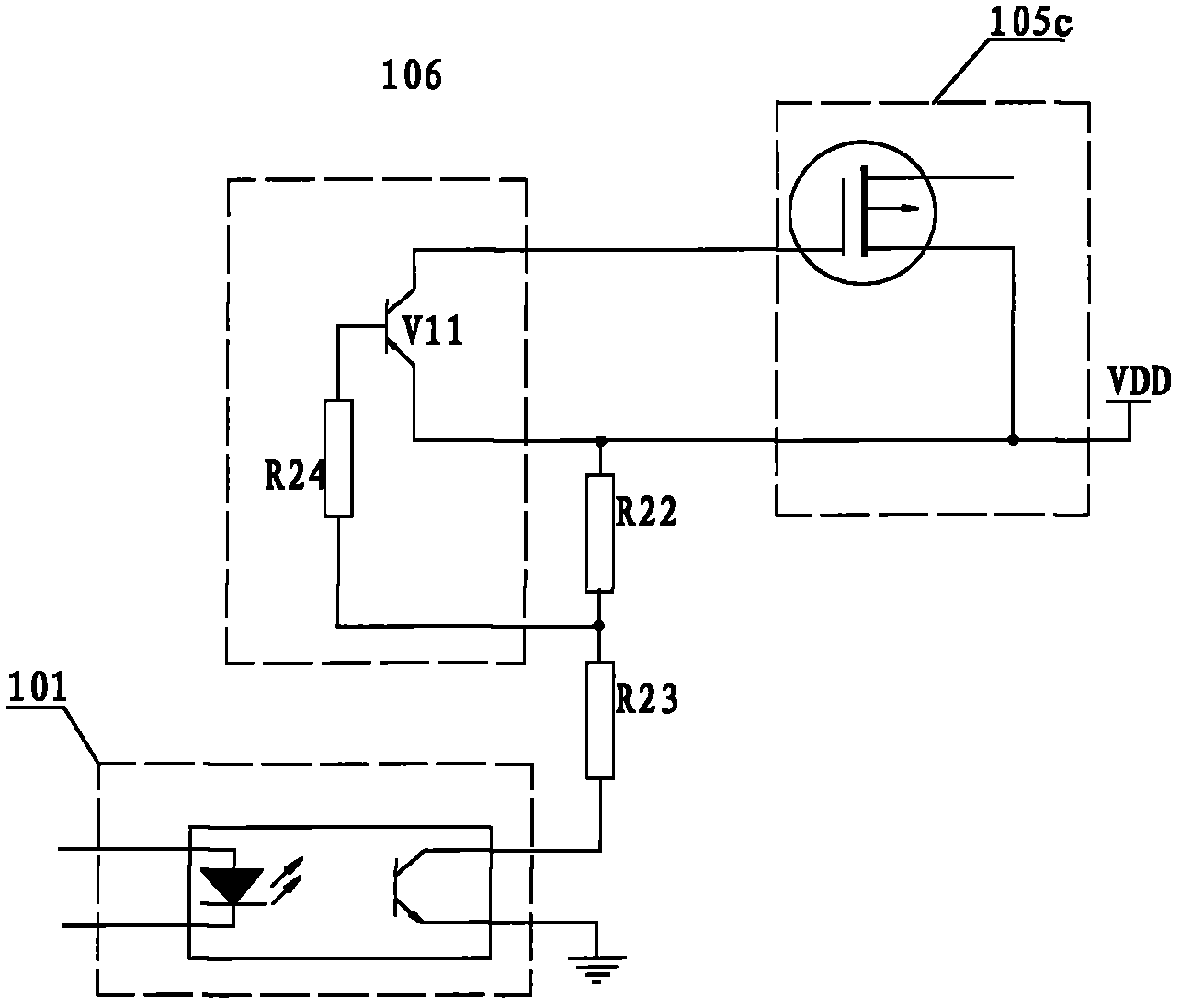
[0027] Such as figure 1 The H bridge drive control circuit shown is mainly composed of core H bridge drive unit 105, drive control units 102 and 108, anti-interference units 103 and 106, protection units 104 and 107, photoelectric isolation units 101 and 108 and the same power supply 110 constitute. Wherein, the H-bridge driving unit 105 is mainly composed of four field effect transistors, and the four field effect transistors include two P-channel field effect transistors 105a and 105c located on the upper arm and two N-channel field effect transistors 105b and 105d located on the lower arm . Wherein, the field effect transistor 105a of the left upper arm and the field effect transistor 105d of the right lower arm constitute branch one, and the field effect transistor 105c of the right upper arm and the field effect transistor 105b of the left lower ...


PUM


Abstract

The invention relates to an H-bridge driving control circuit of a motor, which comprises an H-bridge driving circuit, a driving control unit, an anti-interference unit and a protection unit, wherein in the H-bridge driving unit, two diagonal branch circuits are formed by four switching tubes; the driving control unit is used for converting an input control signal into a suitable voltage for controlling to switch on the corresponding switching tube; the anti-interference unit is used for preventing the upper arm switching tube of the other branch circuit from being switched on when one branch circuit is in the switch-on state; and the protection unit is used for preventing the lower arm switching tube of the other branch circuit from being switched on when one branch circuit is in the switch-on state. The H-bridge driving control circuit of the invention prevents the P switching tube which cannot be switched on from being switched on due to starting of the motor or burr generated by transient large current, improves the anti-interference capacity of the circuit, and can rapidly switch off the corresponding N-channel switching tube when the circuit control signal is disordered or goes wrong, so that the circuit has through protection function. The whole driving control circuit is driven by a single power supply, is easy to implement and has a simple structure, and the reliable work of the circuit is further guaranteed.

Description

technical field [0001] The invention relates to an H bridge drive control circuit of a motor. Background technique [0002] The power drive circuit of the motor is usually driven by an H-bridge structure. The H-bridge drive circuit is driven by four power switch MOS tubes. The upper arm is two P-channel MOS tubes, and the lower arm is two N-channel MOS tubes. Control the conduction and cut-off of the four switch tubes to make the motor rotate forward, reverse or stop. [0003] The patent application with application number 200820122809.1 and titled "H-bridge DC motor drive circuit" discloses an H-bridge DC motor drive circuit, which uses separate logic gates to control the H-bridge. The disadvantages of this circuit are: first, the ability to resist electromagnetic interference is weak; second, when the motor is started, it is easy to cause interference to the control signal, resulting in false conduction of the field effect tube; third, the logic gate circuit needs to prov...

Claims


Application Information

Patent Timeline
IPC IPC(8): H02P1/22H02P7/28
Inventor 许育林姚莉李金宝黄艳辉
Owner SUZHOU R&D CENT OF NO 214 RES INST OF CHINA NORTH IND GRP
Why Eureka
Try Eureka