Hybrid vehicle drive unit

A hybrid vehicle and drive device technology, which is applied to hybrid vehicles, power units, pneumatic power units, etc., can solve the problems of longer shaft length, larger structure, poor mounting ability, etc. The effect of shortening the axial length and preventing the mutual influence of vibration

Active Publication Date: 2014-01-01
HONDA MOTOR CO LTD
View PDF11 Cites 1 Cited by
  • Summary
  • Abstract
  • Description
  • Claims
  • Application Information

AI Technical Summary

Problems solved by technology

[0004] However, if the engine and the generator are arranged coaxially as described in Patent Document 1, the outer diameter of the generator cannot be set larger due to the restriction of the matching surface with the engine, so in order to obtain the necessary rotation To increase the torque and output, it is necessary to increase the axial dimension. However, in this case, the axial length will become longer and the loadability will be poor.
In addition, since the generator and the motor are arranged side by side, the structure becomes large when viewed from the side, and the mountability is poor

Method used


Image

  • Hybrid vehicle drive unit
  • Hybrid vehicle drive unit
  • Hybrid vehicle drive unit

Examples


Embodiment Construction

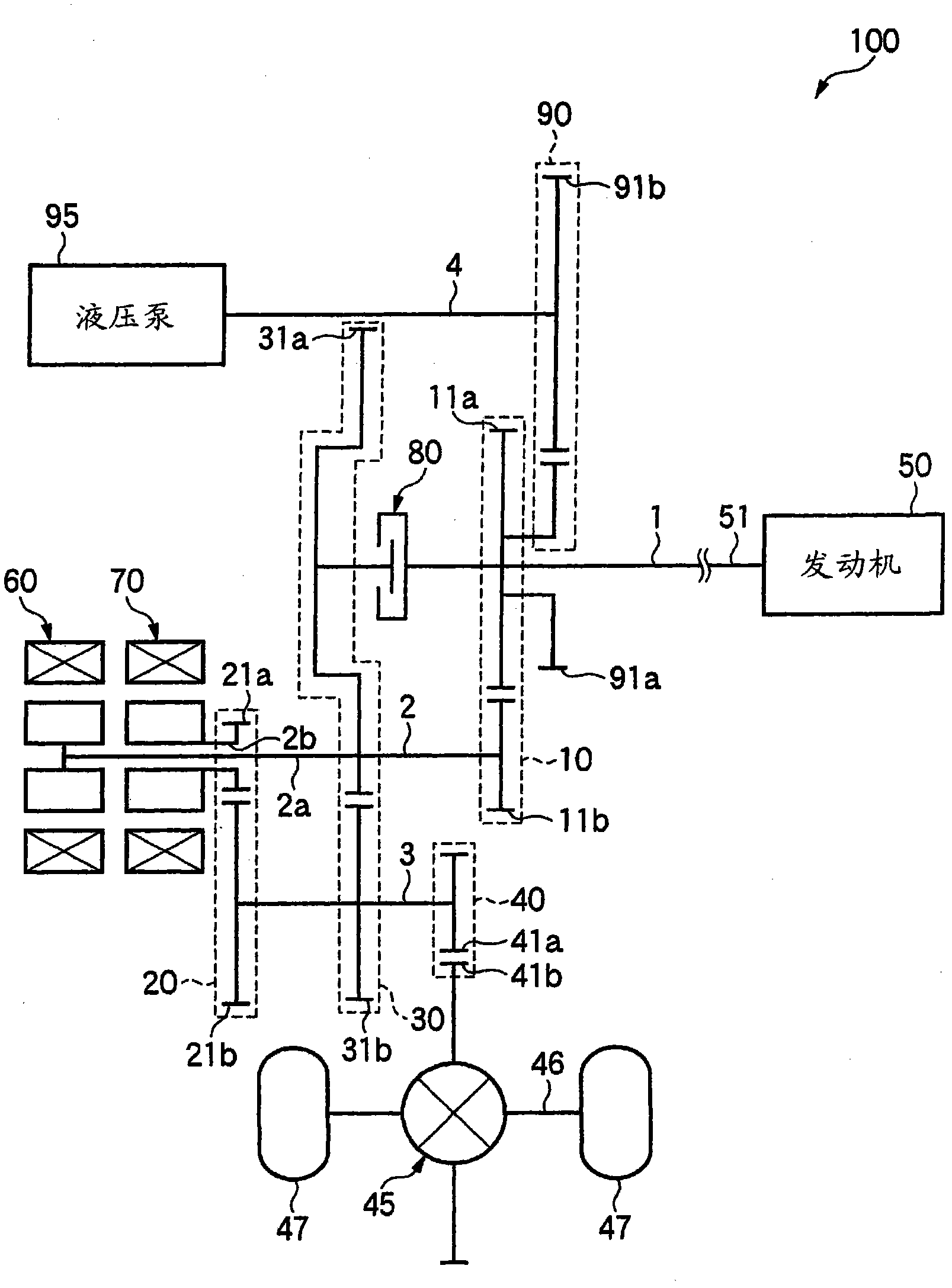
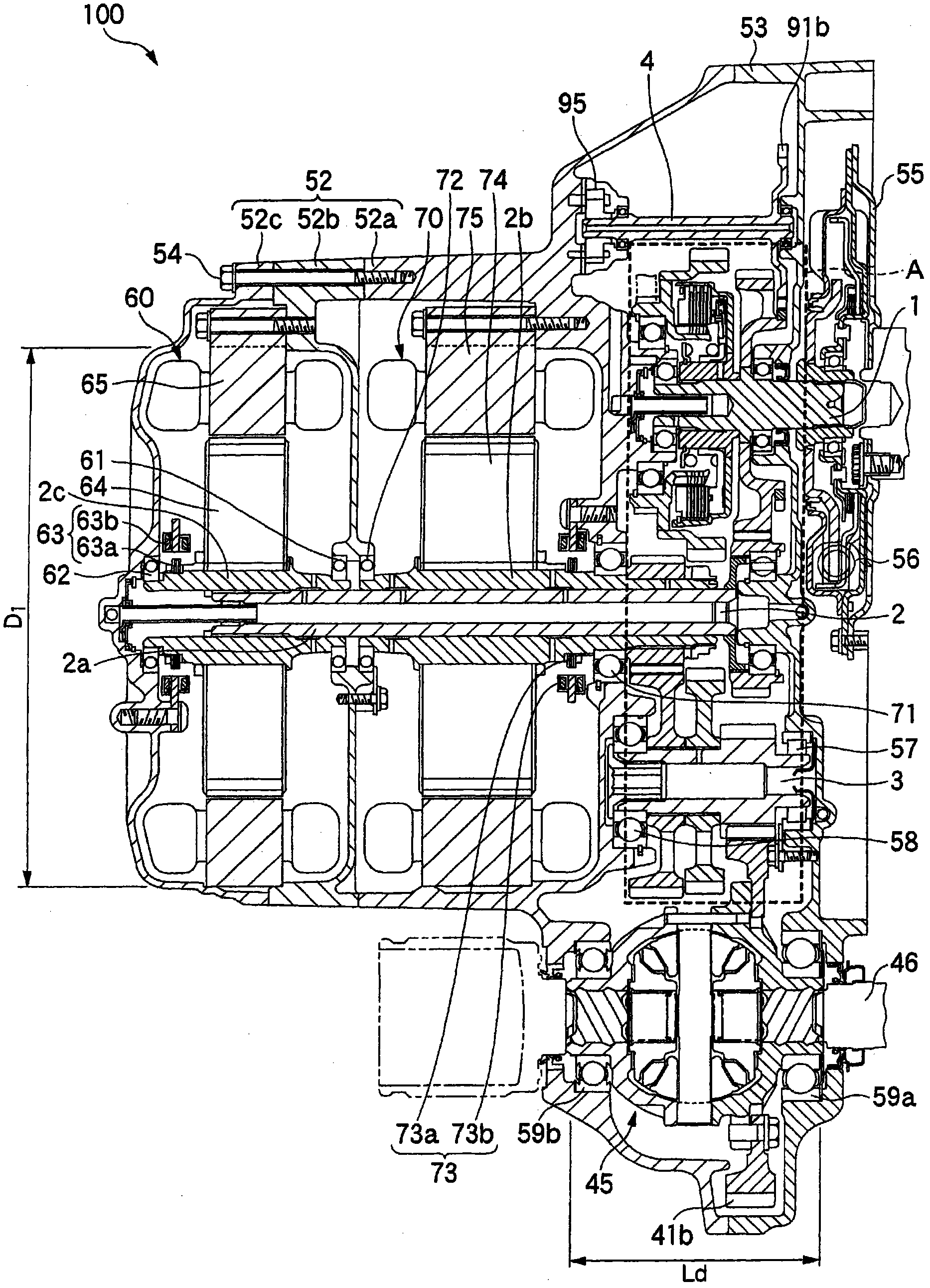
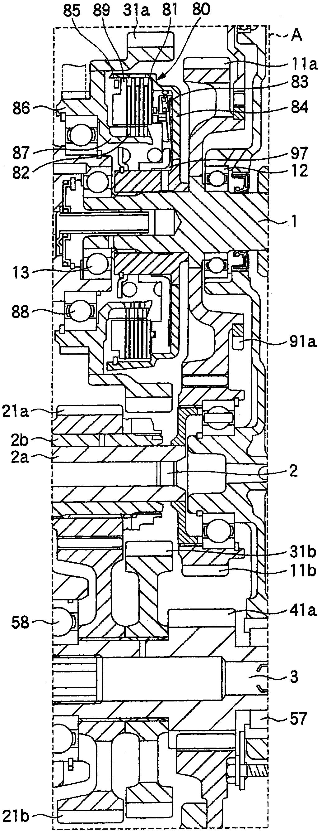
[0034] Hereinafter, preferred embodiments of a drive system for a hybrid vehicle according to the present invention will be described in detail with reference to the drawings. figure 1 is a schematic schematic diagram of a driving device for a hybrid vehicle according to the present invention, figure 2 is a cross-sectional view of a drive device for a hybrid vehicle according to the present invention, image 3 yes figure 2 A magnified view of part A of the Figure 4 is showing figure 2 An explanatory diagram of the relationship of the transmission mechanism of the hybrid vehicle drive unit.

[0035] Such as figure 1 As shown, the driving device 100 for a hybrid vehicle according to the present invention has an engine shaft 1 (first shaft), a generator shaft 2 (second shaft), and an idle shaft 3 (third shaft) arranged in parallel. The shaft 2 has at least an inner peripheral shaft 2a and a hollow outer peripheral shaft 2b (first outer peripheral shaft) mounted so as to ...


PUM


Abstract

A driving apparatus for a hybrid vehicle 100 includes an engine shaft 1, a generator shaft 2 and an idler shaft 3, which are arranged in parallel. The generator shaft 2 includes at least an inner shaft 2a and a hollow outer shaft 2b which is attached rotatably relative to the inner shaft 2a. The engine shaft 1 connected to the crank shaft 51 of an engine 50 is engaged, through a generator driving gear 10, to the inner shaft 2a which is coaxially provided with a generator 60. The outer shaft 2b of the generator shaft 2 which is coaxially provided with a motor 70 is engaged to the idler shaft 3 through a motor driving force transmission gear 20. The engine shaft 1 and idler shaft 3 are engaged to each other through an engine driving force transmission gear 30. The idler shaft 3 and a differential device 45 are engaged each other through a final gear 40. The differential device 45 is connected to driving wheels 47, 47 through a differential axels 46. The engine shaft 1 has a clutch 80 which serves to engage or disengage the power between the engine shaft 1 and idler shaft 3 through the engine driving force transmission gear 30.

Description

technical field [0001] The present invention relates to a driving device for a hybrid vehicle, and more particularly, to a driving device for a hybrid vehicle including an engine, a motor, and a generator. Background technique [0002] As a vehicle drive device including an engine, a motor, and a generator, for example, a vehicle drive device described in Patent Document 1 is known. This driving device for a hybrid vehicle discloses a structure in which the engine and the generator are coaxially arranged (coaxial arrangement) in consideration of the vehicle mountability, and the generator and the motor are arranged in parallel, thereby shortening the length of the power transmission system. full length. [0003] Patent Document 1: Japanese Patent Application Laid-Open No. 8-91065 [0004] However, if the engine and the generator are arranged coaxially as described in Patent Document 1, the outer diameter of the generator cannot be set larger due to the restriction of the m...

Claims


Application Information

Patent Timeline
Patent Type & Authority Patents(China)
IPC IPC(8): B60K6/36B60K6/26B60K6/387B60K6/40B60K6/405B60K6/442B60L50/16
CPCY02T10/6217B60L2270/145Y02T10/70Y02T10/6234B60L11/14B60L11/123Y02T10/7077B60K6/36B60K6/40B60K6/405B60K6/442B60W2550/402B60L50/61B60L50/16B60W2556/50Y02T10/62Y02T10/7072
Inventor 本多健司汤本俊行
Owner HONDA MOTOR CO LTD
Why Eureka
Try Eureka