Gas analyzing apparatus with built-in calibration gas cell

An analysis device and gas chamber technology, applied in the field of gas analysis devices, can solve the problems of theoretical consistency, limited optical adjustment, etc., and achieve the effect of high accuracy

Inactive Publication Date: 2011-04-06
SHIMADZU SEISAKUSHO CO LTD
View PDF7 Cites 24 Cited by
  • Summary
  • Abstract
  • Description
  • Claims
  • Application Information

AI Technical Summary

Problems solved by technology

However, the optical adjustment is limited, making it difficult to fully agree with the theory

Method used


Image

  • Gas analyzing apparatus with built-in calibration gas cell
  • Gas analyzing apparatus with built-in calibration gas cell
  • Gas analyzing apparatus with built-in calibration gas cell

Examples


Embodiment Construction

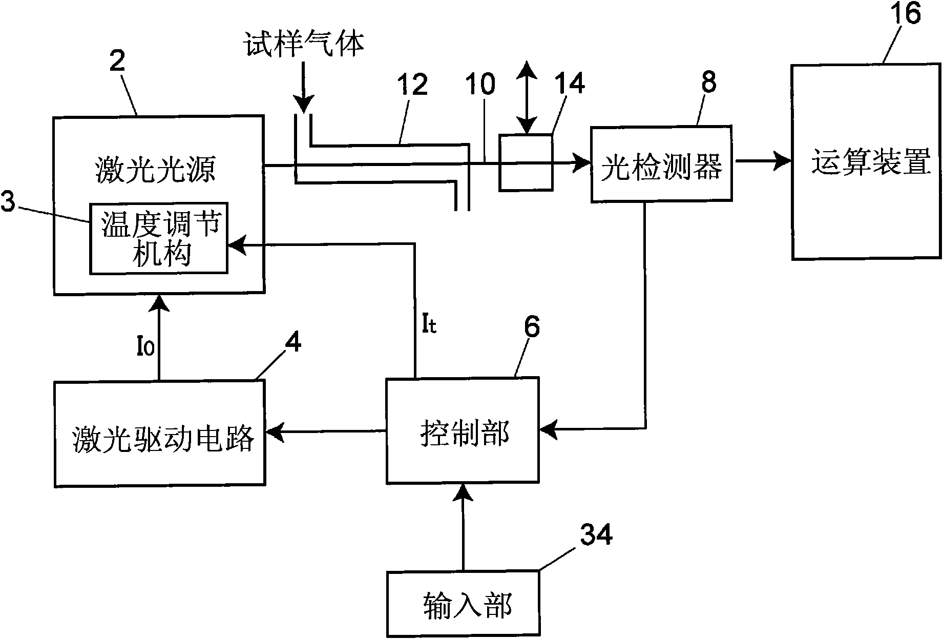
[0044] figure 1 An analysis device according to one embodiment is schematically shown. In the present embodiment, the laser light source 2 that generates laser light as measurement light having a specific wavelength absorbed by a measurement object component in the sample gas is a DFB laser diode capable of changing wavelength. The type of laser light source capable of changing the wavelength is not particularly limited. In order to adjust the temperature of the laser body of the laser light source 2, the laser light source 2 incorporates a temperature adjustment mechanism 3 composed of a Peltier element.

[0045] The laser light source drive control device for controlling the drive of the laser light source 2 includes a laser drive circuit 4 and a control unit 6 composed of an arithmetic processing circuit or a dedicated computer or a general-purpose personal computer. The laser driving circuit 4 provides a fixed reference current Io as a driving current for driving the la...


PUM


Abstract

A gas analyzing apparatus for laser absorption spectroscopy measurement includes a laser light source to generate laser beam with a specific wavelength absorbed by a component being measured in sample gas, a laser light source drive controller to control driving of the laser light source, an optical detector arranged at a location where the laser beam is received, a gas cell for measurement of the sample gas which is arranged on an optical path of the laser beam going from the laser light source to the optical detector, and a computing unit to calculate a concentration of the component being measured in the sample gas in accordance with a detection signal of the optical detector. Further, the gas analyzing apparatus has at least one calibration gas cell where calibration gas is filled with, and a calibration gas cell mounting mechanism capable of locating one of the calibration gas cells in a removable manner on the optical path of the laser beam.

Description

technical field [0001] The invention relates to a gas analysis device using laser absorption spectroscopy technology. Background technique [0002] In the case of gas measurement using laser absorption spectroscopy, the concentration can be theoretically obtained basically according to the Lambert-Beer law. However, optical adjustments are limited, making it difficult to fully agree with theory. As far as reality is concerned, generally zero gas and a gas with known concentration are used to make a calibration curve, and the absorbance is converted into a concentration. [0003] At this time, the calibration gas is introduced into the measurement gas cell (Gas Cell), and sensitivity calibration is performed based on the output. In other methods, a separate optical system, a calibration gas cell, and a photodetector are always provided, and a part of the laser light used as measurement light is separated and taken out by a half-mirror and introduced into the calibration gas...

Claims


Application Information

Patent Timeline
Patent Type & Authority Applications(China)
IPC IPC(8): G01N21/39G01N21/27
CPCG01N21/39G01N2201/1285G01N2021/399G01N21/276
Inventor 松田直树森谷直司
Owner SHIMADZU SEISAKUSHO CO LTD
Why Eureka
Try Eureka