Multi-branch pipe gas-liquid separator

A phase separator and separator technology, which is applied in separation methods, dispersed particle separation, liquid degassing, etc., can solve the safety impact of conventional gas-liquid separator separation effect metering equipment, high one-time investment, and large footprint. problems, to achieve the effect of reducing engineering investment and floor space, wide application and small equipment volume

Active Publication Date: 2011-04-13
BC P INC CHINA NAT PETROLEUM CORP +1
View PDF4 Cites 7 Cited by
  • Summary
  • Abstract
  • Description
  • Claims
  • Application Information

AI Technical Summary

Problems solved by technology

At present, downstream processing stations generally adopt two schemes to receive upstream oil and gas media. One is a slug flow trap, which has the advantages of large processing capacity and strong adaptability, and is often used in the development of large oil and gas fields. The disadvantage is that it is disposable The investment is high, often tens of millions. Once the gas field development plan changes, it is easy to cause waste of investment. At the same time, it occupies a large area and is not suitable for stations with narrow terrain; the other is conventional horizontal or vertical gravity gas-liquid separation The device has a small processing capacity and a narrow processing range, and can only meet the requirements of gas-liquid separation accuracy within a certain range. In the middle and late stages of gas field development, due to the large increase in water content, it often cannot meet the requirements of actual production and operation.
In addition, during the pigging operation of the mixed transportation pipeline, the slug flow generated by the pigging can easily have a serious impact on the separation effect of the conventional gas-liquid separator and the safety of the downstream metering equipment.

Method used


Image

  • Multi-branch pipe gas-liquid separator
  • Multi-branch pipe gas-liquid separator
  • Multi-branch pipe gas-liquid separator

Examples


Embodiment Construction

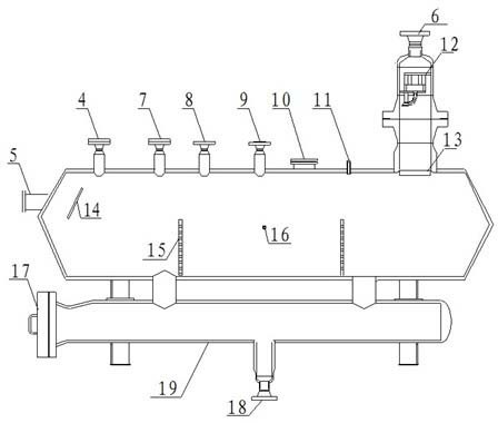
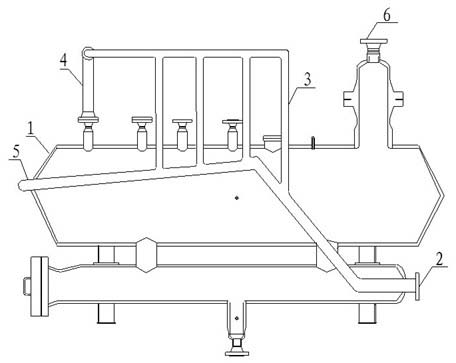
[0010] A manifold gas-liquid two-phase separator, such as figure 1 with figure 2 As shown, it includes: separator cylinder 1, gas-liquid inlet 2, air inlet branch pipe 3, gas phase inlet main pipe 4, liquid phase inlet 5, separator outlet 6, safety valve port 7, manual vent valve port 8, note Nozzle 9, manhole 10, pressure sensor interface 11, filter separation element 12, wire mesh mist catcher 13, buffer baffle 14, rectifier plate 15, liquid level gauge interface 16, ash removal port 17, sewage outlet 18, effusion Barrel 19. in:

[0011] A gas-liquid inlet 2 is arranged near the lower right side of the liquid accumulation cylinder 19, and the gas-liquid inlet 2 is connected with the gas-liquid intake manifold. The gas-liquid intake manifold is divided into an ascending pipe section and a descending pipe section. degrees to 45 degrees, the inclination range of the descending pipe section is -3 degrees to -15 degrees, and two to six vertically upward intake branch pipes ar...


PUM

PropertyMeasurementUnit
angleaaaaaaaaaa
angleaaaaaaaaaa

Abstract

The invention discloses a multi-branch pipe gas-liquid separator. The separator comprises a separator cylinder body and a liquid-accumulating cylinder, wherein a gas-liquid inlet is formed at the position close to the right side of the liquid-accumulating cylinder and is connected with a gas-liquid inlet header pipe; the gas-liquid inlet header pipe is divided into an ascending pipe section tail and a descending pipe section; gas inlet branch pipes are arranged at the tail end of the ascending pipe section and the head of the descending pipe section of the gas-liquid inlet header pipe respectively; the gas inlet branch pipes are arranged above the separator cylinder body and are connected first to positions parallel to separator cylinder body and then to a gas phase inlet header pipe; and the tail end of the descending pipe section of the gas-liquid inlet header pipe is connected with a liquid phase inlet arranged at the upper left of the separator cylinder body. The separator has the advantages of effectively capturing the slug flow formed in a pipe conveying and cleaning process and achieving the effect of quick, safe and effective separation.

Description

technical field [0001] The invention relates to a gas-liquid separation device, in particular to a multi-branch gas-liquid two-phase separator with slug flow capture function specially used for oil and gas fields in petroleum and petrochemical industry systems. Background technique [0002] In recent years, large oil and gas fields and oil and gas bearing structures have been discovered successively in the vast coastal areas and the western Gobi and desert areas. However, the natural environmental conditions are very harsh, and it is difficult to carry out engineering construction on site, and the required engineering investment and management costs are also extremely high. Therefore, in order to carry out development and construction efficiently, safely and economically, the country vigorously develops the multiphase flow transportation technology, and the oil and gas media are mixed and transported to the downstream processing station for treatment through a pipeline. At ...

Claims


Application Information

Patent Timeline
Patent Type & Authority Applications(China)
IPC IPC(8): B01D50/00B01D19/00
Inventor 杨强刘永茜边云燕郭佳春陈静郭艳林李小丽张莉黄静余洋冯琦雒定明李积科文成杨宋德琦秦兴述杨晓秋陈彰兵郭成华向波
Owner BC P INC CHINA NAT PETROLEUM CORP
Why Eureka
Try Eureka