Heat radiator and manufacturing method thereof

A technology for radiators and heat dissipation sections, applied in indirect heat exchangers, manufacturing tools, heat exchange equipment, etc., can solve the problems of time-consuming and labor-consuming production and assembly, easy loosening, poor heat dissipation efficiency, etc., and achieve simple and fast assembly , low-cost effect

Active Publication Date: 2011-04-13
GIGA BYTE TECH CO LTD
View PDF0 Cites 6 Cited by
  • Summary
  • Abstract
  • Description
  • Claims
  • Application Information

AI Technical Summary

Problems solved by technology

However, each heat dissipation unit in its heat dissipation fin group only relies on a small area of ​​narrow strips at the bottom to absorb heat from the heat conduction base plate, so the overall heat dissipation efficiency is not good
Moreover, the heat dissipation fin group only uses solder paste or heat-conducting adhesive to bond the bottom surface to the heat-conducting bottom plate, so its lateral bearing capacity is relatively poor.
Therefore, the stability of the combination of the two is not good, and it is easy to loosen.
[0003] Taiwan Announcement No. M337724 patent discloses a sandwich type heat dissipation module, although it can improve the above-mentioned problem of poor stability in combination, and each heat dissipation unit of the heat dissipation fin group relies on the parts in contact with the copper sandwich components on both sides and The part where the bottom surface is in contact with the copper base conducts heat. Although it has a larger heat conduction area, the overall heat dissipation rate is better than the above.
However, its multiple metal fins and copper sandwich components need to be tightly locked together by bolts, so the production and assembly are time-consuming and labor-intensive

Method used


Image

  • Heat radiator and manufacturing method thereof
  • Heat radiator and manufacturing method thereof
  • Heat radiator and manufacturing method thereof

Examples


Embodiment Construction

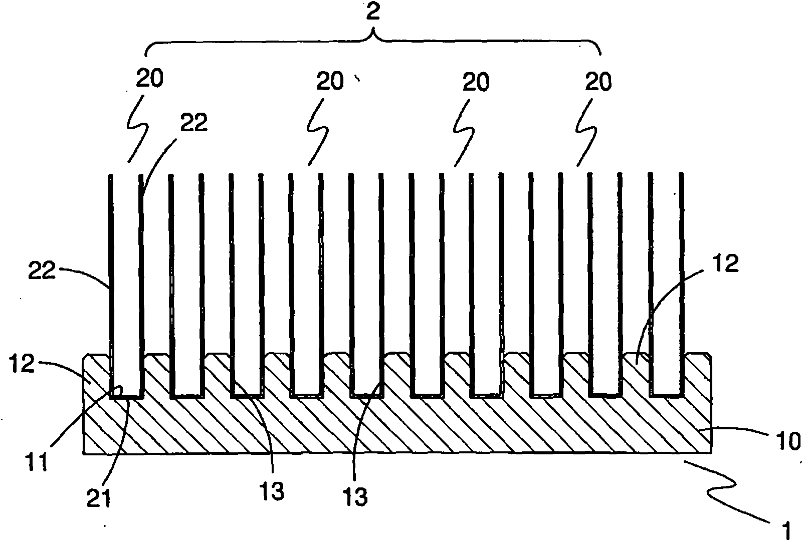
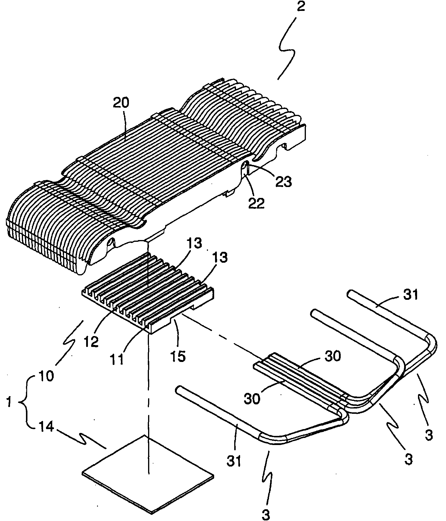
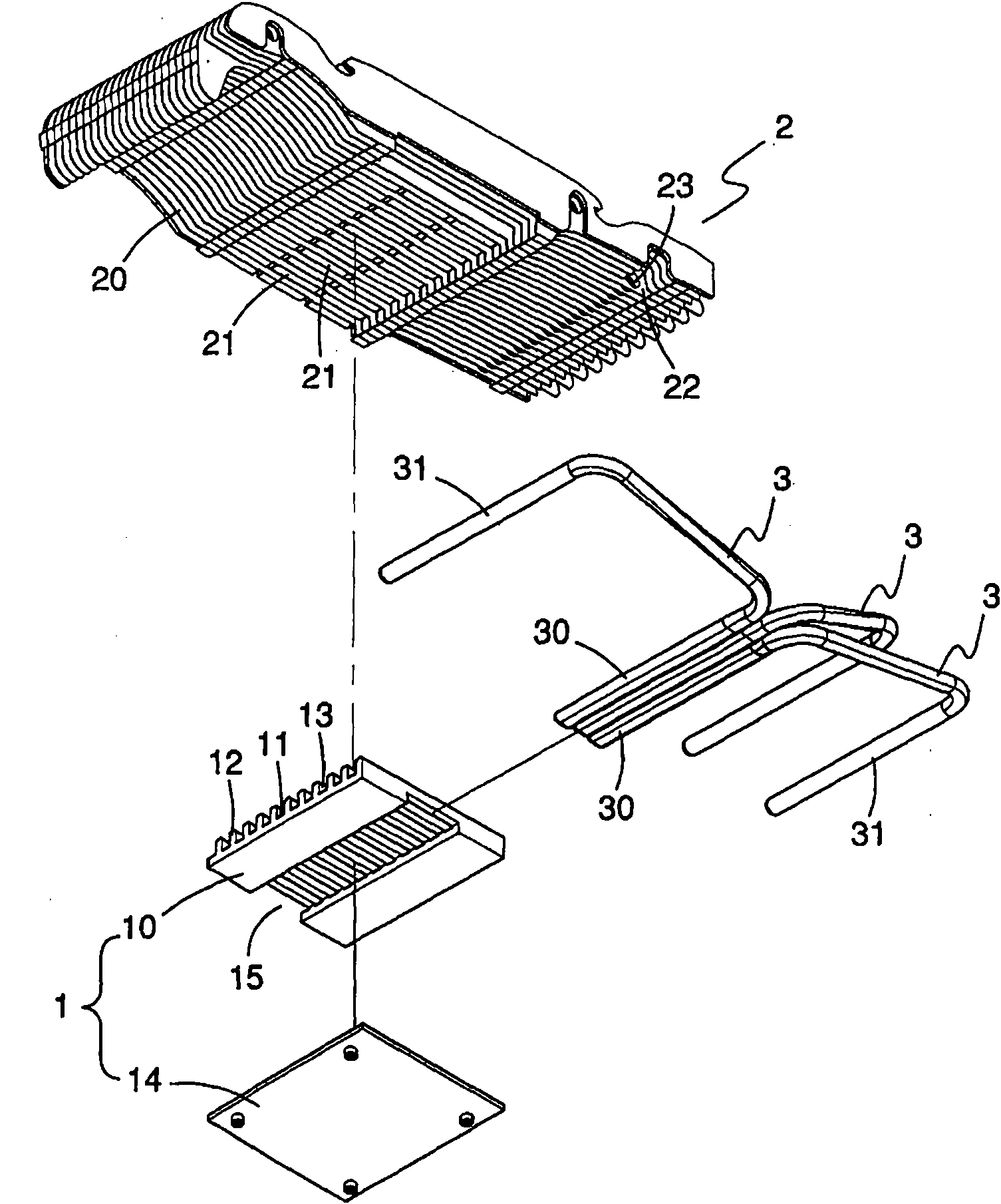
[0020] figure 1 The first embodiment of the heat sink of the present invention is shown, which indicates that the heat sink includes a heat conducting plate 1 and a heat dissipation fin set 2 . in:

[0021] The heat conduction plate 1 includes a first plate 10 made of heat conduction metal, the first plate 10 has a flat top surface 11 and a plurality of protrusions 12 formed on the top surface 11 of the first plate 10 side by side at intervals. Two long sides of each protrusion 12 respectively have a wide surface 13 opposite to each other.

[0022] The heat dissipation fin set 2 includes a plurality of heat dissipation units 20 , and each heat dissipation unit 20 includes a base plate 21 and two side plates 22 , and the two side plates 22 are vertically connected to two opposite long sides of the base plate 21 . The bottom sheet 21 of each cooling unit 20 is closely attached to the top surface 11 of the first board 10 . Parts of the two side sheets 22 of each heat dissipati...


PUM


Abstract

The invention relates to a heat radiator, which comprises a heat conducting plate and a heat radiating fin group. The heat conducting plate comprises a first plate, and the top surface of the first plate is provided with a plurality of lugs arranged side by side at intervals. The heat radiating fin group comprises a plurality of heat radiating units, each heat radiating unit is provided with a bottom sheet and two side sheets, the bottom sheets are appressed to the top surface of the first plate, and the two side sheets are partially appressed onto the adjacent lugs. In the invention, the bottom surface of the first plate can be provided with a transverse trench penetrating to the top surface so as to ensure that the bottom sheets of the heat radiating units are exposed in the transverse trench, the heat radiator comprises a plurality of heat pipes arranged in the transverse trench and appressed to the bottom sheets of the heat radiating units, and the heat conducting plate comprises a second plate combined onto the bottom surface of the first plate. A preferable manufacturing method of the heat radiator comprises the steps of: embedding each heat radiating unit between every two adjacent lugs correspondingly; coating solder paste in the transverse trench; assembling the heat pipes in the transverse trench; coating the solder paste on the top surface of the second plate and covering the top surface of the second plate at the bottom surface of the first plate; and heating the solder paste to weld the structural members into a whole.

Description

technical field [0001] The invention relates to a heat sink, in particular to a heat sink with good heat dissipation effect, good stability, simple manufacture and assembly and a manufacturing method thereof. Background technique [0002] Taiwan Patent Publication No. M346014 discloses a common heat sink structure, which is mainly composed of a heat dissipation fin set and a heat conduction bottom plate, and the two are combined with solder paste or heat conduction glue. However, each heat dissipation unit in the heat dissipation fin set only relies on a small area of ​​long and narrow fins at the bottom to absorb heat from the heat conduction bottom plate, so the overall heat dissipation efficiency is not good. Moreover, the heat dissipation fin assembly only uses solder paste or heat conduction adhesive to bond the bottom surface to the heat conduction bottom plate, so its lateral bearing capacity is relatively poor. Therefore, the stability of the combination of the two ...

Claims


Application Information

Patent Timeline
Patent Type & Authority Applications(China)
IPC IPC(8): F28F3/06F28D15/02B23K1/00
CPCF28D15/0275
Inventor 黄顺治毛黛娟
Owner GIGA BYTE TECH CO LTD
Why Eureka
Try Eureka