
Substrate integrated waveguide split ring resonator-based microwave band pass filter

A substrate-integrated waveguide and split resonant ring technology, applied to waveguide devices, waveguides, circuits, etc., to achieve the effects of steep out-of-band attenuation, small size, and light weight

Active Publication Date: 2014-03-19
ZTE CORP
View PDF3 Cites 0 Cited by
  • Summary
  • Abstract
  • Description
  • Claims
  • Application Information

AI Technical Summary

Problems solved by technology

[0007] So far, no one has combined the substrate-integrated waveguide split resonator ring with the double-sided parallel stripline structure to design a microwave bandpass filter with a double-layer hollow structure.

Method used


Image

  • Substrate integrated waveguide split ring resonator-based microwave band pass filter
  • Substrate integrated waveguide split ring resonator-based microwave band pass filter
  • Substrate integrated waveguide split ring resonator-based microwave band pass filter

Examples


Embodiment Construction

[0042] The technical solutions of the present invention will be described in detail below in conjunction with the accompanying drawings and preferred embodiments. The following examples are only used to illustrate and explain the present invention, but not to limit the technical solution of the present invention.

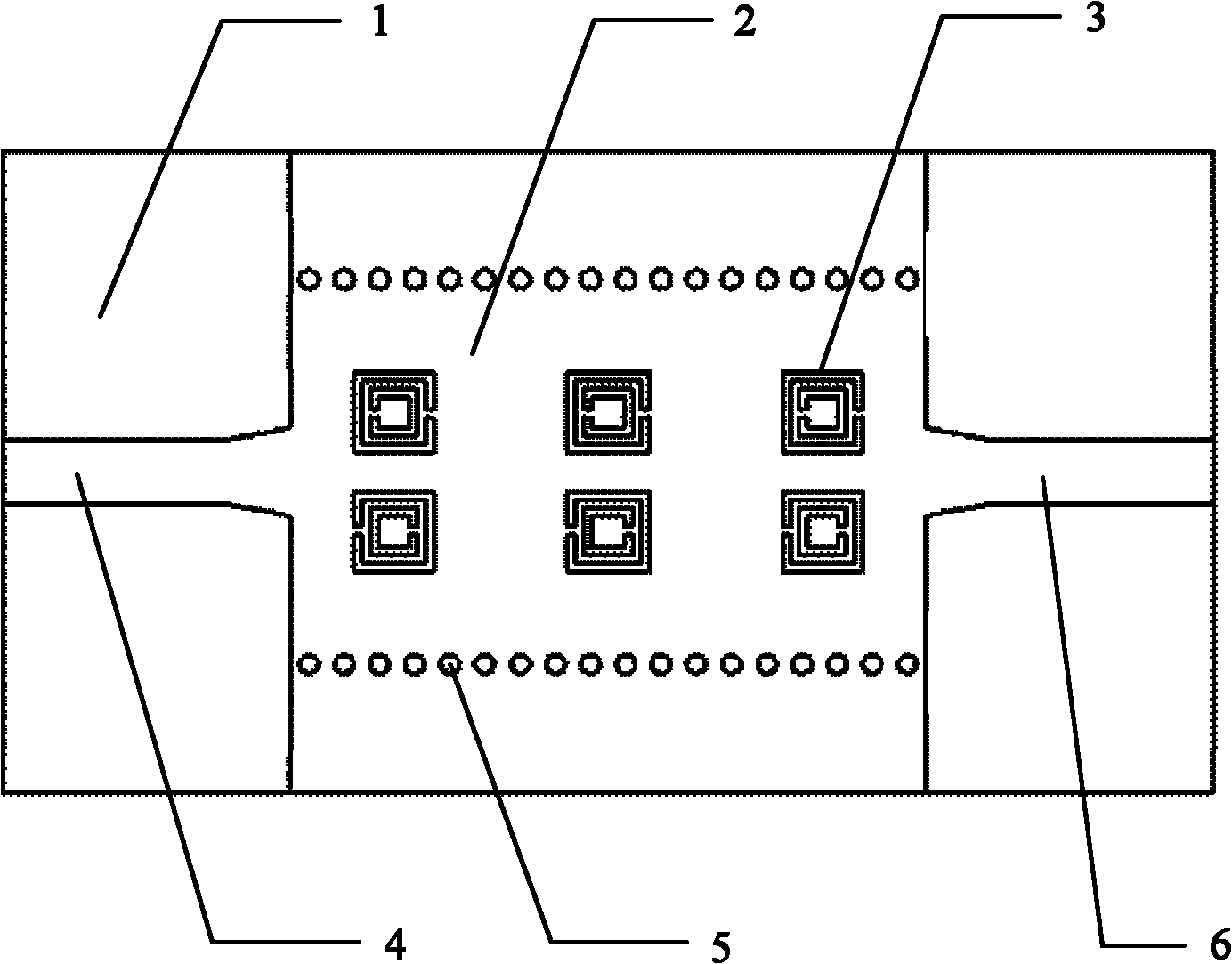
[0043] Such as figure 1 Shown is an embodiment of the microwave bandpass filter based on the substrate integrated waveguide split resonator provided by the present invention, including:

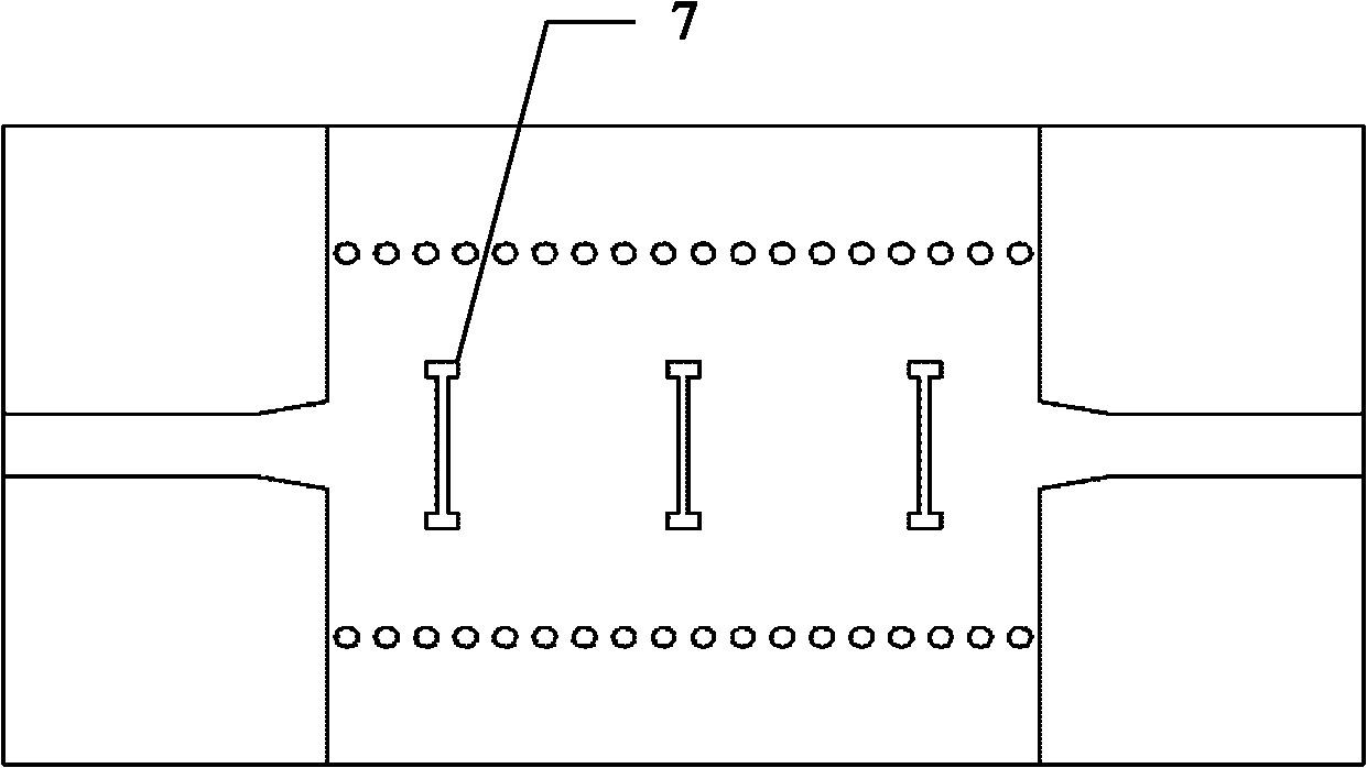
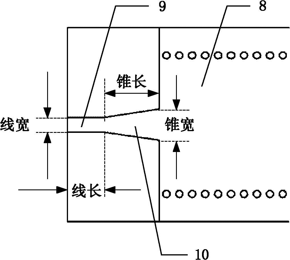
[0044] Two rows of metal columns (5) are fixed on the dielectric substrate (1), and each row of metal columns (5) is arranged horizontally at equal intervals to form a substrate-integrated waveguide (2); both ends of the substrate-integrated waveguide (2) are connected There is a microstrip feeder (4), (6), and the surfaces of the microstrip feeder (4), (6) and the substrate integrated waveguide (2) are metal media; the upper surface of the substrate integrated waveguide (2) is lo...


PUM


Abstract

The present invention provides a microwave bandpass filter and a method for designing a microwave bandpass filter. The microwave bandpass filter includes a substrate integrated waveguide comprising two rows of metallic components fixed on a dielectric substrate. A microstrip feed line is connected to each of the two ends of the substrate integrated waveguide; the surfaces of said microstrip feed lines and said substrate integrated waveguide are metallic media. An array of opening resonator rings of row m×column n is etched on the upper surface of said substrate integrated waveguide between said two rows of metallic components. A row of dumbbell shape or the deformation of said dumbbell shape is etched on the lower surface of said substrate integrated waveguide between said two rows of metallic components and corresponding to each column of opening resonator rings. With a steep out-band attenuation, a small volume, a light weight, a large power capacity, and easy integration with other planar microwave and millimeter wave circuits, the bandpass filter designed by above mentioned method thereby is hopeful to be adequately applied in microwave and millimeter wave hybrid integrated circuits or millimeter wave integrated circuits.

Description

technical field [0001] The invention relates to a microwave filter in a microwave and millimeter-wave hybrid integrated circuit (MMIC, Microwave and Millimeter-wave Integrated Circuits) or a millimeter-wave integrated circuit (MIC), in particular to a microwave bandpass filter based on a substrate-integrated waveguide split resonant ring structure device. Background technique [0002] Microwave filter is an important microwave device in microwave engineering. It is widely used in microwave systems to pass the microwave frequency band that is allowed to pass and cut off the microwave frequency band that is not allowed to pass. [0003] Commonly used microwave filters are implemented with rectangular waveguides or microstrip lines. However, traditional design ideas often make the size of the filter device a bottleneck for development. Especially in some designs with relatively high requirements, it will be more difficult to realize it by using traditional design ideas. Amon...

Claims


Application Information

Patent Timeline
Patent Type & Authority Patents(China)
IPC IPC(8): H01P1/20H01P1/203H01P11/00
CPCH01P3/121H01P1/207H01P1/2088
Inventor 李超
Owner ZTE CORP
Learn More