Method for acquiring channel state information, base station and user equipment

A technology of channel state information and user equipment, which is applied in the field of wireless technology transmission, can solve problems such as ungiven antenna calibration, and achieve the effects of wide application range, easy implementation, and high efficiency

Inactive Publication Date: 2011-04-13
SHARP KK
View PDF3 Cites 99 Cited by
  • Summary
  • Abstract
  • Description
  • Claims
  • Application Information

AI Technical Summary

Problems solved by technology

However, this document does not give a solution on how to use SRS to perform antenna calibration on FDD (Frequency Division Multiplexing) CoMP systems and estimate accurate CSI

Method used


Image

  • Method for acquiring channel state information, base station and user equipment
  • Method for acquiring channel state information, base station and user equipment
  • Method for acquiring channel state information, base station and user equipment

Examples


no. 1 example

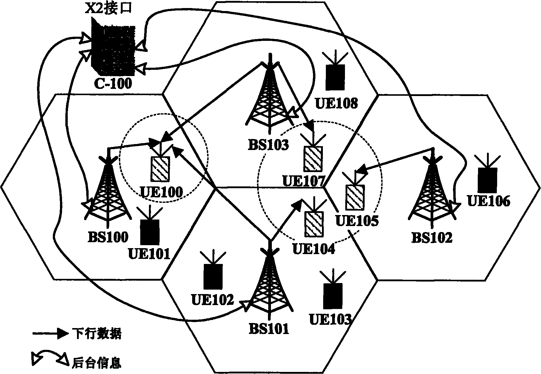
[0107] Figure 8 A schematic diagram showing a method for acquiring CSI based on cell SRS in a downlink CoMP coordinated beamforming (CoMP-CB) transmission system according to the first embodiment of the present invention. Such as Figure 8 As shown, base stations BS600, BS601, and BS602 are serving base stations for user equipment UE600, UE601, and UE602 respectively, base stations BS601, BS602 are cooperative base stations for user equipment UE600, base stations BS600, BS602 are cooperative base stations for user equipment UE601, and base stations BS600, BS601 It is the coordinated base station of the user equipment UE602, and the three base stations BS600, BS601, and BS602 send data to the three user equipment UE600, UE601, and UE602 respectively through cooperation between beams, thereby forming a downlink CoMP coordinated beamforming (CB, Coordinated Beam- forming) transmission scheme to achieve the purpose of improving the data throughput at the edge of the wireless cel...

no. 2 example

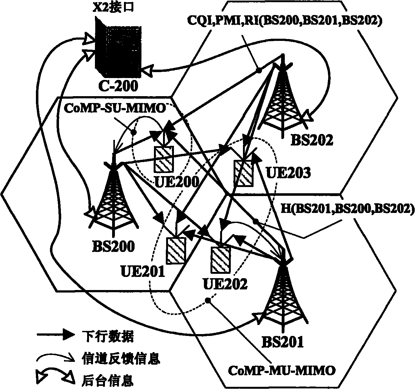
[0143] Figure 10 A schematic diagram showing a method for acquiring CSI of a CoMP-based SRS in downlink CoMP-MU-MIMO according to the second embodiment of the present invention is shown. Such as Figure 10 As shown, base stations BS700, BS701, and BS702 are serving base stations for user equipment UE700, UE701, and UE702 respectively, base stations BS701, BS702 are cooperative base stations for user equipment UE700, base stations BS700, BS702 are cooperative base stations for user equipment UE701, and base stations BS700, BS701 It is the cooperative base station of the user equipment UE702. The base stations BS700, BS701, and BS702 respectively adopt 2, 1, and 1 transmitting antennas, and the user equipments UE700, UE701, and UE702 respectively adopt 2, 1, and 1 receiving antennas, which together constitute a Downlink 4×4 multi-user MIMO (MU-MIMO), cooperatively sending downlink data to three user equipments UE700, UE701, and UE702, thereby forming a downlink CoMP multi-user...

no. 3 example

[0167] Figure 17 A schematic diagram showing a method for acquiring CSI of an SRS based on a CoMP Set in uplink CoMP-MU-MIMO according to a third embodiment of the present invention. Such as Figure 17 As shown, base stations BS800, BS801, and BS802 are serving base stations for user equipment UE800, UE801, and UE802 respectively, base stations BS801, BS802 are cooperative base stations for user equipment UE800, base stations BS800, BS802 are cooperative base stations for user equipment UE801, and base stations BS800, BS801 It is the cooperative base station of user equipment UE802. User equipment UE800, UE801, and UE802 use 1, 1, and 1 transmitting antenna respectively, and base stations BS800, BS801, and BS802 respectively use 1, 1, and 1 receiving antenna to form a Uplink 3×3 multi-user MIMO (MU-MIMO), cooperatively sending uplink data to three base stations BS800, BS801, and BS802, thus forming an uplink CoMP multi-user MIMO (CoMP-MU-MIMO) transmission scheme to improve ...


PUM


Abstract

The invention discloses a method for acquiring channel state information, a base station and user equipment. In the invention, CoMP (Coordinated Multi-Point) user equipment can adopt an SRS (Sounding Reference Signal) mode based on a service cell or an SRS mode based on CoMP. The base station detects uplink SRS transmitted by the user equipment and acquires the channel state information according to the detected SRS. Then, the base station performs resource scheduling together with other base stations on the basis of the channel state information required by the resource allocation, exchanges scheduling information and / or data required to be transmitted cooperatively after joint resource scheduling with other base stations and carries out the transmitting mode selection, power allocation and transmitter optimization together with the other base stations. Finally, the base station transmits data and / or signaling to the user equipment. The invention has the characteristics of simple structure, completion and high efficiency and is easy for realization.

Description

technical field [0001] The present invention relates to the field of wireless technology transmission, in particular to a method for acquiring channel state information based on a sounding reference signal (SRS), a base station and user equipment. Background technique [0002] Since personal or mobile communication devices have been required to have broadband services such as multimedia services, online games, video-on-demand, and mobile TV, wider system frequency bands, higher peak rates, and better edge service quality have become the future personal or mobile communication devices. An important requirement for communication systems. 3GPP (Third Generation Partnership Project) is an international organization dedicated to standardization of personal or mobile communications. The 3GPP organization began to design EUTRA (Evolved Universal Mobile Telecommunications System and Terrestrial Radio Access Network) and EUTRAN (Evolved Universal Mobile Telecommunications System Net...

Claims


Application Information

Patent Timeline
Patent Type & Authority Applications(China)
IPC IPC(8): H04L1/06
Inventor 梁永明黄磊刘仁茂丁铭张应余杨曾
Owner SHARP KK
Why Eureka
Try Eureka