Radio frequency identification method and radio frequency identification system

A radio frequency identification and tag identification technology, applied in the field of radio frequency identification, can solve the problems of high work energy consumption, affecting the use of tags, waste of energy consumption, etc., achieving the effect of large wireless network capacity, reducing power consumption, and improving positioning accuracy

Inactive Publication Date: 2011-04-13
深圳市悦宏旭昂科技有限公司
View PDF6 Cites 45 Cited by
  • Summary
  • Abstract
  • Description
  • Claims
  • Application Information

AI Technical Summary

Problems solved by technology

[0006] At present, the three frequency bands of high frequency, ultra high frequency and microwave are widely used, but each frequency band cannot be widely used due to its own limitations.
[0007] Among them: the low-frequency band adopts FSK, ASK and other modulation technologies, which have obvious boundary effects, and can control the effective recognition distance within the specified range, but due to its low transmission rate, it is impossible to realize two-way transmission of large amounts of data in high-speed moving objects interact
[0008] Among them: the 13.56MHz high-frequency band recognition distance is only 80 cm at most, and long-distance recognition cannot be realized
[0009] Among them: ultra-high frequency band, the international typical use frequency is 915MHz, which is divided into two frequency bands of 840MHz-845MHz and 920MHz-925MHz in my country, the theoretical recognition distance is 20 meters, but due to the poor anti-metal ability, the actual working distance is only 3-8 meters
[0010] Among them: the

Method used


Image

  • Radio frequency identification method and radio frequency identification system
  • Radio frequency identification method and radio frequency identification system
  • Radio frequency identification method and radio frequency identification system

Examples


Embodiment 1

[0061] This embodiment discloses a radio frequency identification system, which includes a low-frequency base station 100, an active tag 200, and a high-frequency base station 300, wherein the low-frequency base station 100 is used to generate a low-frequency signal, and the low-frequency signal includes the low-frequency The low-frequency base station code information of the base station; the active tag 200 is used to receive the low-frequency signal, compare the low-frequency signal with the low-frequency base station code pre-stored in it, and wake up the active tag if the two match A microprocessor module, the microprocessor module instructs the high-frequency module of the active tag to perform information interaction with the high-frequency base station through microwave signals; the high-frequency base station 300 is used to receive and send microwave signals, and the received The information in the microwave signal is forwarded to other devices for use.

[0062] imag...

Embodiment 2

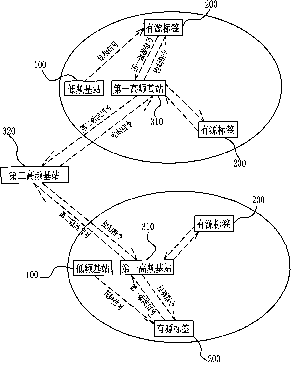
[0067] figure 1 It is a schematic diagram of the principle structure of the radio frequency identification method in a wide range of the present invention. In the figure, the supervision scope is only schematically divided into two sub-regions. It should be noted that it can be divided into multiple sub-regions according to the actual supervision scope; in each The low-frequency base station 100 and the first high-frequency base station 310 are installed in the sub-area, and the size of the sub-area is consistent with the low-frequency coverage size of the low-frequency base station 100 installed in the sub-area. A second high-frequency base station 320 is installed between the central control platform (not shown) of the monitoring and management system.

[0068] The following is the data transmission and interaction process within the regulatory scope:

[0069] 1. When the active tag 200 enters the supervision range, it will receive the low-frequency signal transmitted by th...

Embodiment 3

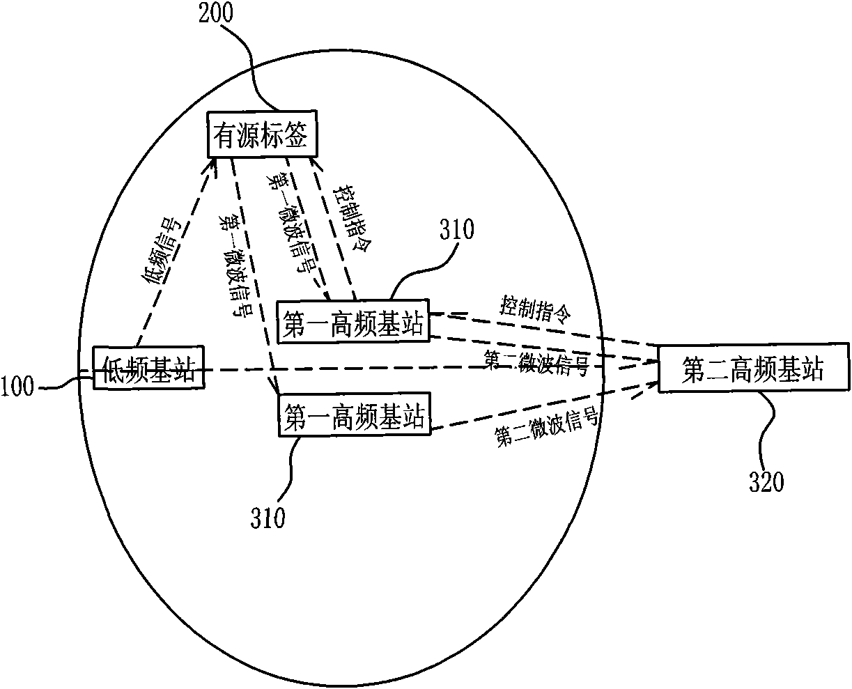
[0110] figure 2 It is a schematic diagram of the principle structure of the narrow-range radio frequency identification method of the present invention, which is suitable for monitoring and management systems with a narrow regulatory scope. As shown in the figure, the supervision area is less than or equal to the low-frequency coverage area of ​​the low-frequency base station 100 installed in this area, and at least two paired first high-frequency base stations 310 are installed in the supervision area. It should be noted that Only two pairs are schematically shown in the figure. Of course, the present invention also includes other multi-pair situations. The antennas of the first high-frequency base stations 310 are all directional antennas, and the directions of each directional antenna are opposite.

[0111] The following is the data transmission and interaction process within the regulatory scope:

[0112] 1. When the active tag 200 enters the supervision area, it will re...


PUM


Abstract

The invention relates to a radio frequency identification technology and particularly discloses a radio frequency identification method and a radio frequency identification system, which are applied in a monitoring management system for personnel, vehicles, commodities and the like. In the invention, by adopting a low-frequency awakening and information verification technology, an active tag can be subjected to high-frequency communication only within a low-frequency coverage area and does not need to work in other time, which reduces electric consumption of above 99% of time, therefore, the power supply of high-capacity batteries is not needed so that the size of the tag is further and effectively reduced. Compared with the traditional radio frequency identification technology, by adopting the mode combining the low-frequency identification and microwave signal intensity, the invention effectively improves the positioning precision to a high-speed moving object. The radio frequency identification method and system can realize the full duplex interaction of data, wherein the full duplex data communication between multiple identification objects and an information center can be realized within a large range by utilizing the characteristics of longer microwave communication distance and large wireless network capacity.

Description

technical field [0001] The invention belongs to the technical field of radio frequency identification, and in particular relates to a radio frequency identification method and a radio frequency identification system used in monitoring and management systems for personnel, vehicles and commodities. Background technique [0002] Radio Frequency Identification (RFID) technology is a communication technology that automatically identifies objects (labels) and obtains relevant information through radio frequency signals without establishing mechanical or optical contact between the identification system and the identification objects (labels). [0003] The existing radio frequency identification system is mainly composed of three parts: identification object (label), reader, and antenna. The reader sends a radio wave of a specific frequency to the tag through the antenna to drive the tag to send an internal identification code (ID Code) to the tag. The reader, after receiving the ...

Claims


Application Information

Patent Timeline
IPC IPC(8): H04W16/18H04W48/20G06K17/00
Inventor 邵旭昂何坚
Owner 深圳市悦宏旭昂科技有限公司
Why Eureka
Try Eureka