Heating device, film forming apparatus, film forming method, and device

A heating device and mounting technology, which is applied in the direction of electrical components, semiconductor/solid-state device manufacturing, gaseous chemical plating, etc., can solve the problems of unfree expansion of the device, poor coverage, and inability to apply large substrates such as glass

Inactive Publication Date: 2011-04-13
PHILTECH
View PDF1 Cites 7 Cited by
  • Summary
  • Abstract
  • Description
  • Claims
  • Application Information

AI Technical Summary

Problems solved by technology

For example, ECR (Electron Cycrotron Resonance, Electron Cyclotron Resonance) plasma CVD can also grow films when the substrate temperature is below 300°C, but the coverage is poor, so it is better used for bottom-up (bottom-up) growth
In addition, unlike plasma, ECR plasma has a limitation of microwave wavelength dependence, and device expansion is not free, so it cannot be applied...

Method used


Image

  • Heating device, film forming apparatus, film forming method, and device
  • Heating device, film forming apparatus, film forming method, and device
  • Heating device, film forming apparatus, film forming method, and device

Examples


no. 1 approach

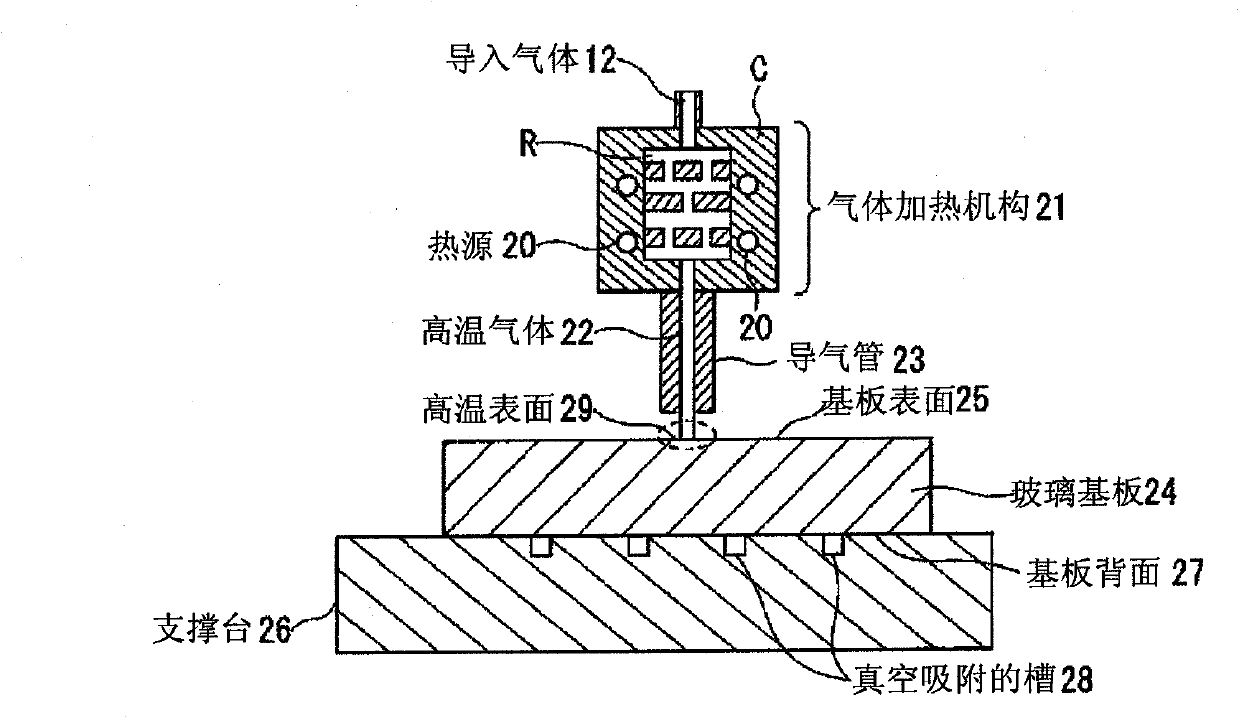
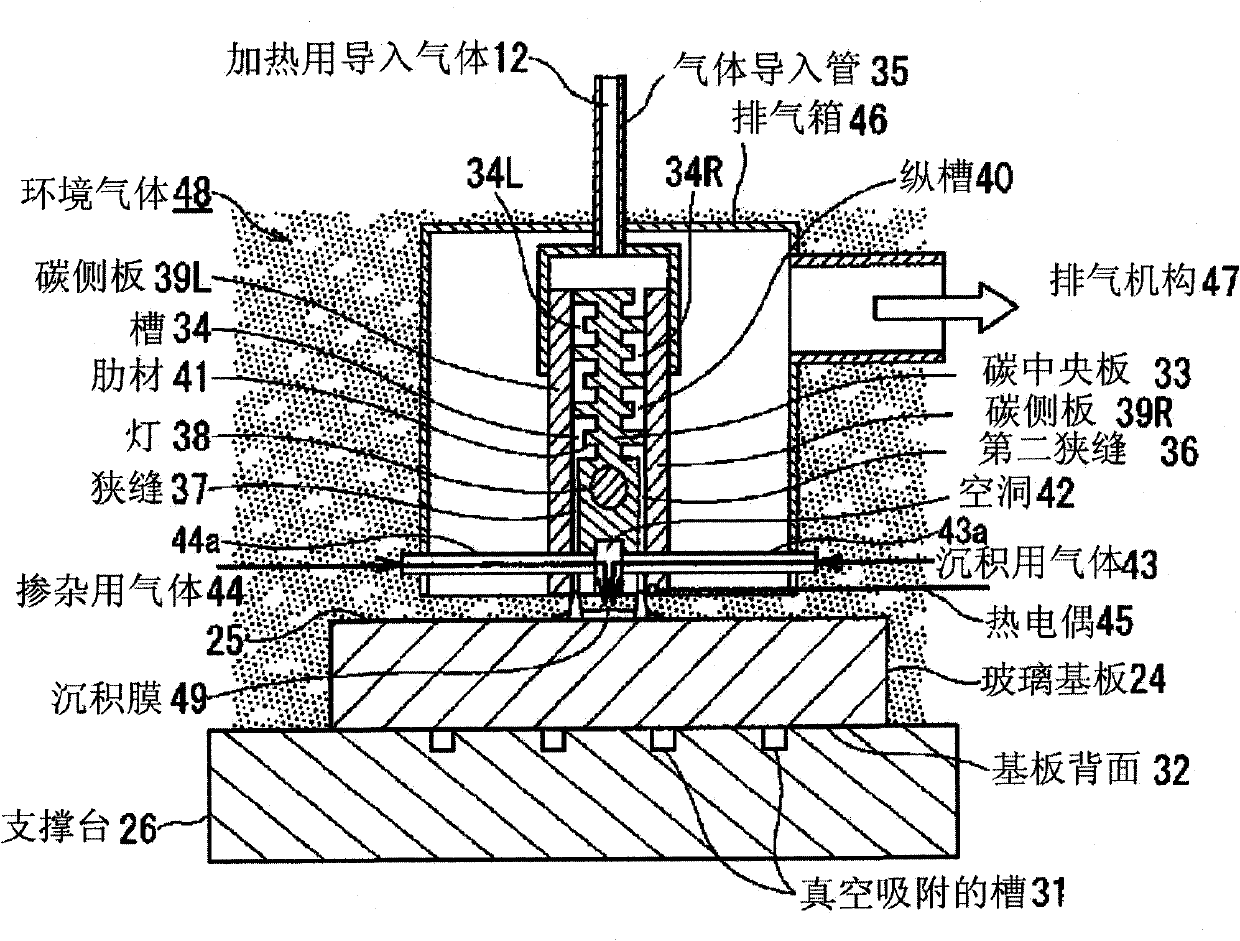
[0115] figure 2 Indicates that it has the same as the figure 1 The shown heating device is a schematic cross-sectional view of a film forming apparatus configured by a heating device based on substantially the same principle. Such as figure 2 As shown, the glass substrate 24 has a thickness of, for example, 0.7 mm, and is tightly placed on the glass substrate supporting table 26 . The support table 26 has a vacuum suction tank 31 therein, which absorbs the glass substrate 24 to effectively make thermal contact, and the temperature of the support table 26 is used to control the temperature of the back surface 32 of the glass substrate 34 .

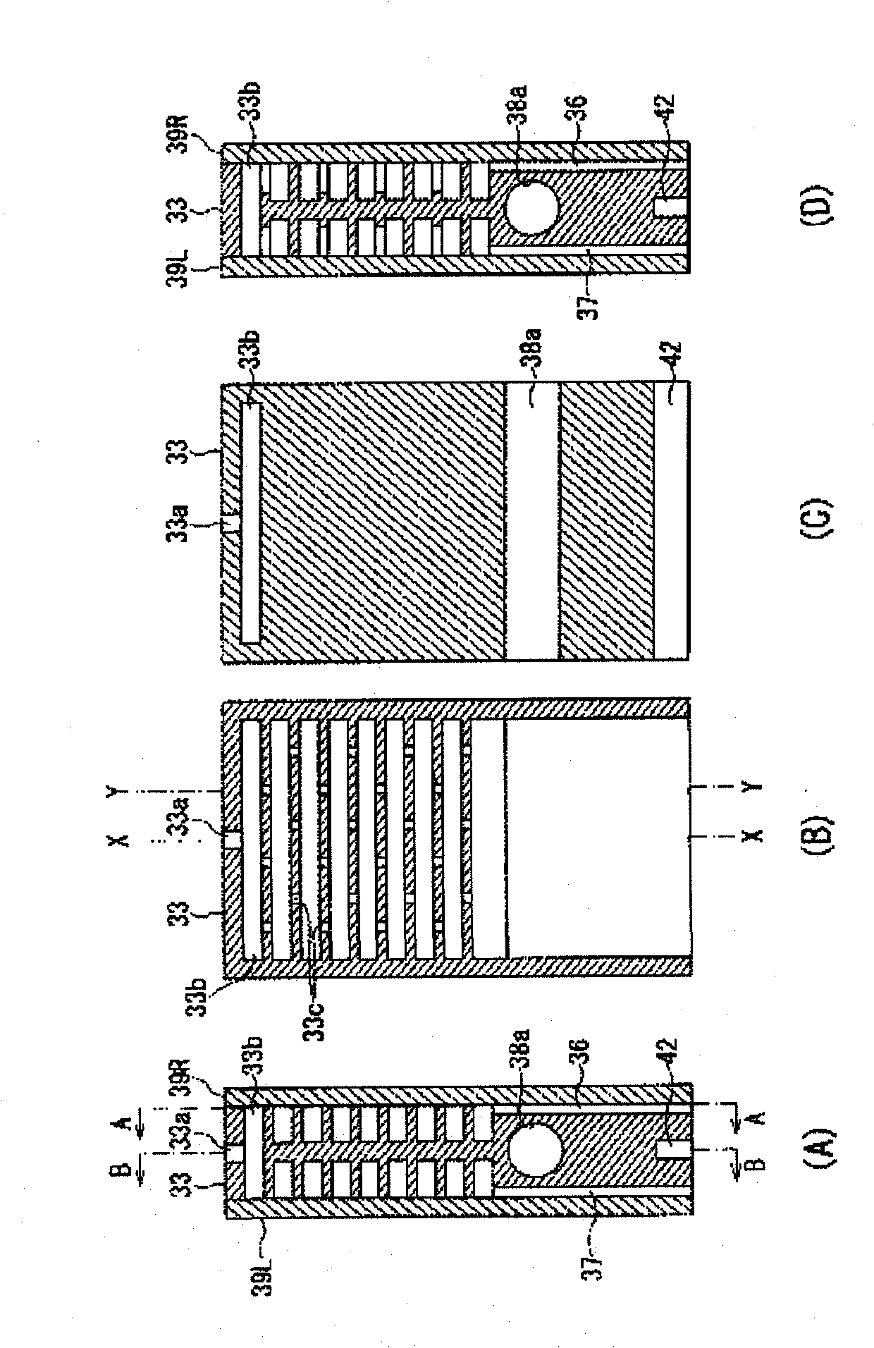
[0116] The heating mechanism of the introduced gas 12 for heating will be described. The heating mechanism has: a solid flat carbon central plate 33 formed of carbon (including, for example, graphite, isotropic carbon, etc.) A pair of left and right carbon side plates 39L, 39R, in the depth direction of the carbon central plate 33 ( ...

no. 2 approach

[0135] Figure 7 is a configuration diagram showing the configuration of the film forming apparatus 111 according to the second embodiment of the present invention, Figure 8 It is an enlarged view of its main part.

[0136] Such as Figure 7 As shown, the film forming apparatus 111 has: a substrate 112 for forming a desired film; a coolable and movable support table 113 supporting the substrate 112 ; and a gas blowing device 114 .

[0137] The substrate 112 is formed of a flat glass substrate or plastic substrate of a desired size, and a silicon oxide film or a silicon oxide film is formed on the surface 112a at a temperature higher than the softening temperature of these substrates 112 (for example, 300°C to 400°C). Films of high-temperature thermal CVD materials such as silicon nitride films and polysilicon are grown.

[0138] The support table 113 is formed on the surface 113a that is in close contact with the back surface 112b of the substrate 112. A plurality of groov...


PUM


Abstract

Provided is a heating device capable of forming a film efficiently on a glass substrate. Also provided is a film forming apparatus having the heating device. The film forming apparatus comprises the heating device for blowing such a high-temperature gas vertically to the surface (25) of a glass substrate (24) placed on a supporting bed (26), as has a temperature higher than the softening point temperature of the glass substrate. The film forming apparatus blows such a depositing gas (43) simultaneously with a high-temperature gas to the surface of the glass substrate, as is thermally decomposed to form a film deposit.

Description

technical field [0001] The present invention relates to a heating device for forming, for example, a silicon thin film on a glass substrate, a film forming device and a film forming method having the heating device. [0002] In addition, the present invention relates to the improvement of film formation suitable for making large-area electronic components. For example, it involves forming a substrate that is not resistant to high temperature, such as a glass substrate or a substrate that has completed the wiring process. A method for growing or heating a film at a high temperature of the supporting platform, such as a silicon film or a silicon oxide film, a silicon nitride film, or a compound film of more than 3 yuan, and a film forming device thereof. Background technique [0003] Generally, as an element having a silicon thin film grown on a glass substrate, there are liquid crystal displays, organic EL (ELectro Luminescence, electroluminescence) displays, solar cells, and...

Claims


Application Information

Patent Timeline
IPC IPC(8): H01L21/205C23C16/452H01L21/31
CPCH01L21/02573H01L21/02595H01L21/02532C23C16/24H01L21/02422C23C16/46C23C16/4557H01L21/0262C23C16/4586C23C16/45595H01L21/67109C23C16/463
Inventor 古村雄二西原晋治村直美
Owner PHILTECH
Why Eureka
Try Eureka