Current detecting circuit and transformer current measuring system

A current detection circuit and current detection technology, applied in the direction of measuring current/voltage, measuring only current, converting DC power input to DC power output, etc., can solve the problems of difficulty in generating accurate analog excitation current and complex analog excitation current generation circuit, etc. , to avoid the complication of circuit structure, avoid the increase of components, and reduce the effect of wrong action

Inactive Publication Date: 2011-04-13
SHINDENGEN ELECTRIC MFG CO LTD
View PDF7 Cites 10 Cited by
  • Summary
  • Abstract
  • Description
  • Claims
  • Application Information

AI Technical Summary

Problems solved by technology

However, in the technique of Patent Document 2, the generation circuit of the analog excitation current is relatively complicated, and it is difficult to generate an analog excitation current with high accuracy.

Method used


Image

  • Current detecting circuit and transformer current measuring system
  • Current detecting circuit and transformer current measuring system
  • Current detecting circuit and transformer current measuring system

Examples


Embodiment approach 1

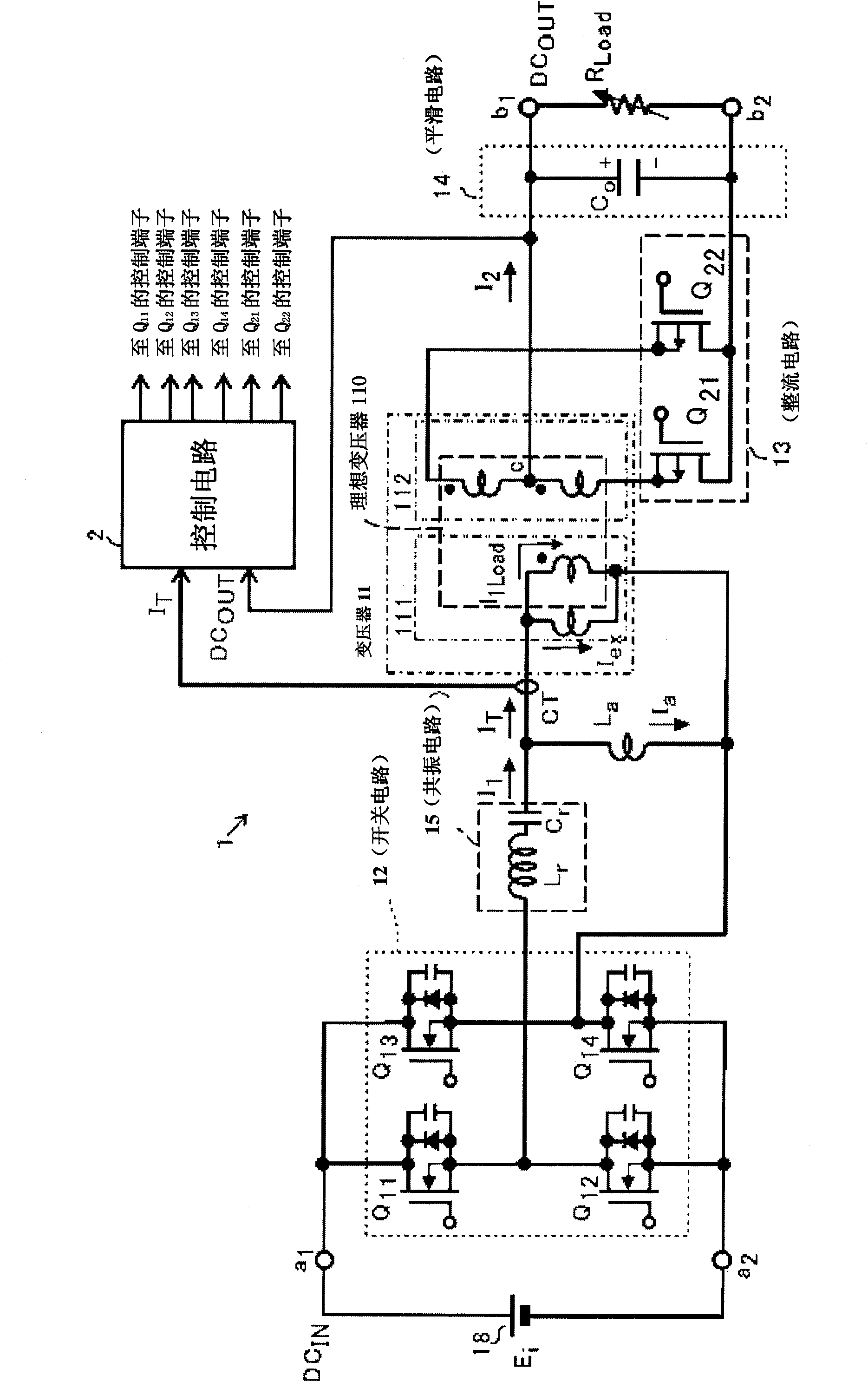
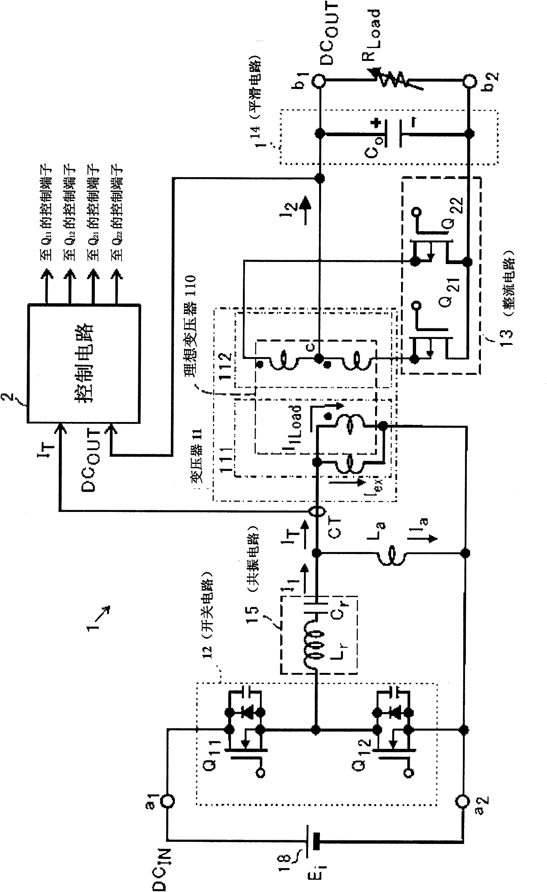
[0059] figure 1 It is a schematic diagram showing a basic form in which the transformer current measurement system according to Embodiment 1 of the present invention is applied to a DC / DC converter using a transformer.

[0060] exist figure 1 Among them, the DC / DC converter 1 has a transformer 11 , a switching circuit 12 , a rectifying circuit 13 , and a smoothing circuit 14 . The DC voltage DC is input to the input terminal of the DC / DC converter 1 IN , DC voltage DC OUT output from the output terminal.

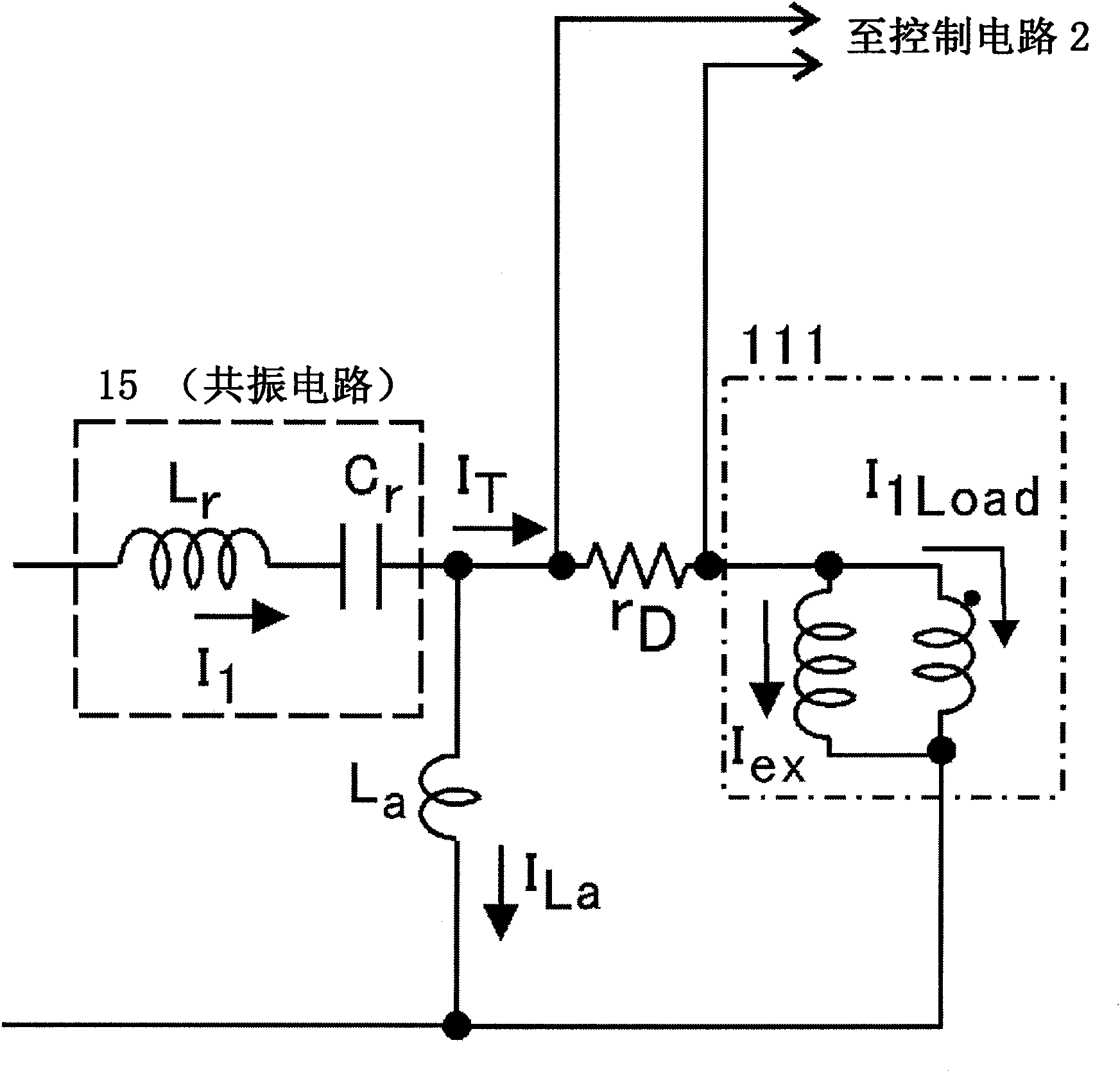
[0061] On the primary coil 111 of the transformer 11, a current detector CT is connected in series, and an inductor L is connected in parallel at the serial connection between the primary coil 111 and the current detector CT. a . The rectification circuit 13 is connected to the secondary coil 112 of the transformer 11 , and the smoothing circuit 14 is connected to the output side of the rectification circuit 13 .

[0062] In addition, in figure 1 , the switch circu...

Embodiment approach 2

[0085] Composition of conversion power supply 1A

[0086] Figure 8 It is a circuit diagram of a switching power supply 1A having a current detection circuit 10 according to Embodiment 2 of the present invention. The switching power supply 1A is a so-called current resonance type switching power supply, and supplies a DC voltage to the load 200 . This conversion power supply 1A has a transformer T, a DC power supply Vin, switching elements Q5, Q6, Q7, Q8, and an inductor L constituting a resonant circuit. r and capacitance C r , a capacitor Co, and a current detection circuit 10 . The current detection circuit 10 has a current detection unit 101 and an inductor L ma , by detecting the current flowing through the primary side of the transformer, the current flowing through the secondary side of the transformer is measured indirectly.

[0087] First, the configuration of the converter power supply 1A provided on the primary side of the transformer T will be described. On t...

Embodiment approach 3

[0101] Structure of conversion power supply 1B

[0102] Figure 10 A circuit diagram of a switching power supply 1B having a current detection circuit 10 according to Embodiment 3 of the present invention. Convert Power 1B with Figure 8 The difference of the switching power supply 1A in Embodiment 2 of the present invention shown is that the inductors that together form the resonant circuit with the capacitor Cr include inductors Lr1 and Lr2, and the connection position of the current detection circuit 10 is different. Here, the same reference numerals are assigned to the same components of the conversion power supply 1B as those of the conversion power supply 1A, and description thereof will be omitted.

[0103] One end of the inductor Lr1 is connected to the source of the switching element Q5 and the drain of the switching element Q6 , and the other end of the inductor Lr1 is connected to one end of the primary coil T1 of the transformer T through the current detection un...


PUM


Abstract

Provided are a current detecting circuit and a transformer current measuring system, wherein transformer currents (primary current and secondary current) can be measured without deteriorating operations of an element and a circuit even when a transformer having a large excitation inductance is used in the cases where the element and the circuit which do not normally operate without using a transformer having a small excitation inductance are connected to the primary side. A current detector (CT) (current transformer) is connected in series to the primary winding (111) of a transformer (11), and an inductor (La) is connected in parallel to the serial connection of the primary winding (111) and the current detector (CT). Based on the value of a primary current (IT) detected by means of the current detector (CT), the secondary current (I2) of the transformer (11) is measured.

Description

technical field [0001] The present invention relates to a technique for measuring the current (primary current or secondary current) flowing in a transformer with a large excitation inductance. Background technique [0002] The technologies we know so far are based on the excitation current through the transformer to avoid the magnetization saturation of the transformer. [0003] exist Figure 11 Among them, the power conversion device 8 has a transformer 81, a switch circuit 82 connected to the primary coil 811 of the transformer 81, a rectifier circuit 83 connected to the secondary coil 812, and a smoothing circuit 84 provided on the output side of the rectifier circuit 83. . exist Figure 11 , the switching circuit 82 consists of a switching element Q 1 constituted, the rectifier circuit 83 is composed of two switching elements Q 21 , Q 22 constitute. Additionally, the smoothing circuit 84 consists of an inductor L O and capacitance C O constitute. [0004] In thi...

Claims


Application Information

Patent Timeline
Patent Type & Authority Applications(China)
IPC IPC(8): H02M3/28G01R19/00H02M1/00
CPCH02M2001/0009G01R19/18G01R19/0092G01R15/185H02M3/335H02M1/40H02M1/0009H02M1/0058Y02B70/10
Inventor 箱田康德小林公祯
Owner SHINDENGEN ELECTRIC MFG CO LTD
Why Eureka
Try Eureka