Sealing device for centrifuge main shaft
A technology of sealing device and centrifuge, which is applied in the direction of engine sealing, centrifuge, mechanical equipment, etc., can solve the problems of iron ion corrosion, material pollution, falling into, etc., and achieve the effect of preventing corrosion and prolonging the service life
- Summary
- Abstract
- Description
- Claims
- Application Information
AI Technical Summary
Problems solved by technology
Method used
Image

Examples
Embodiment Construction
[0019] The present invention will be further described below in conjunction with the embodiment shown in accompanying drawing:
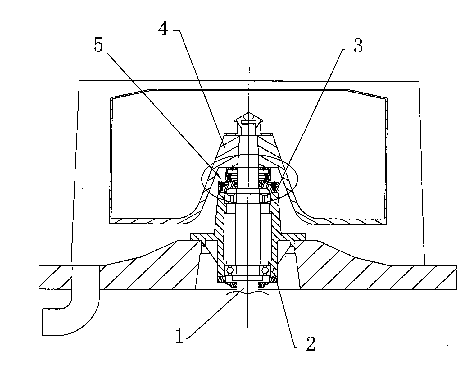
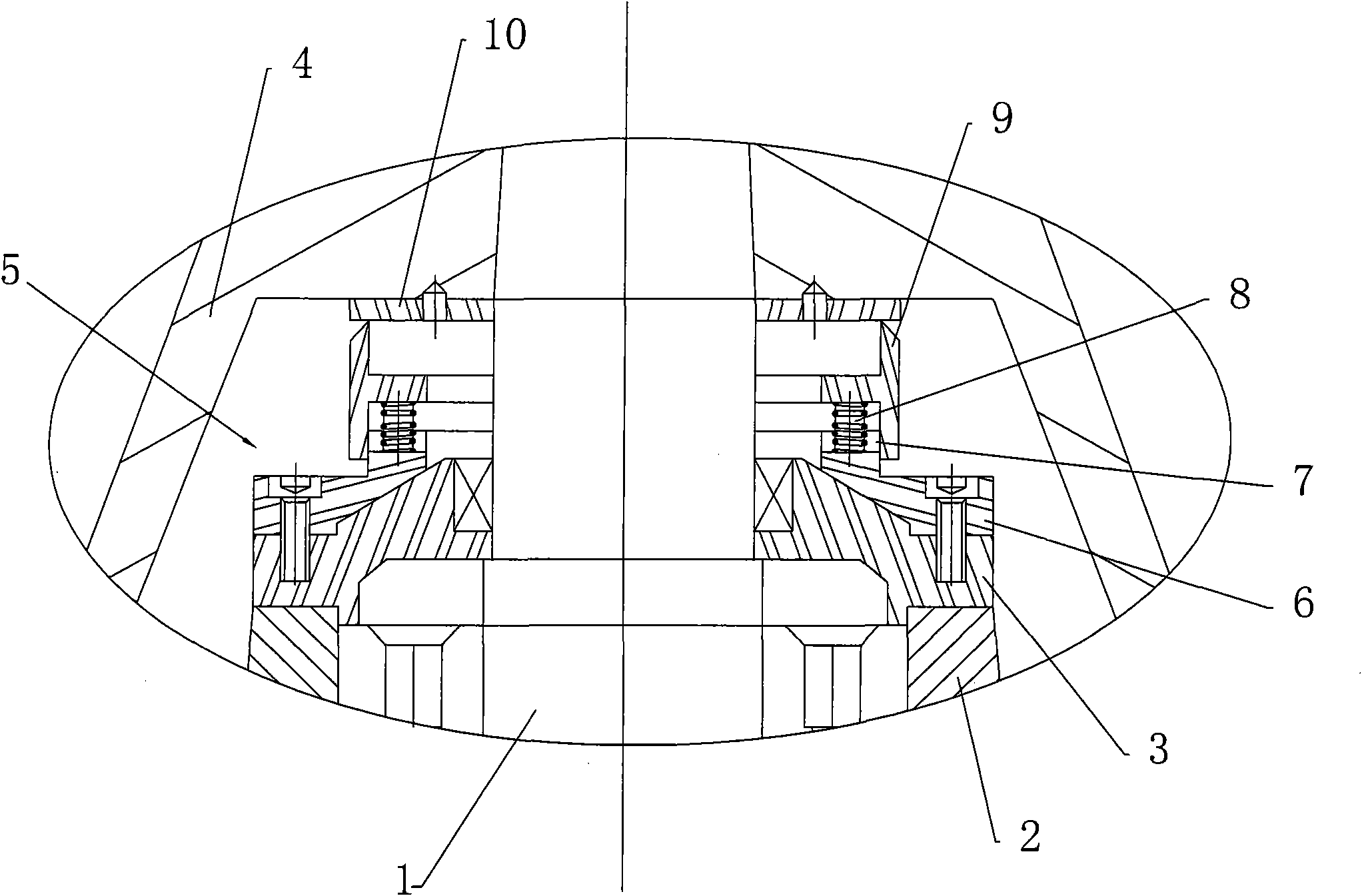
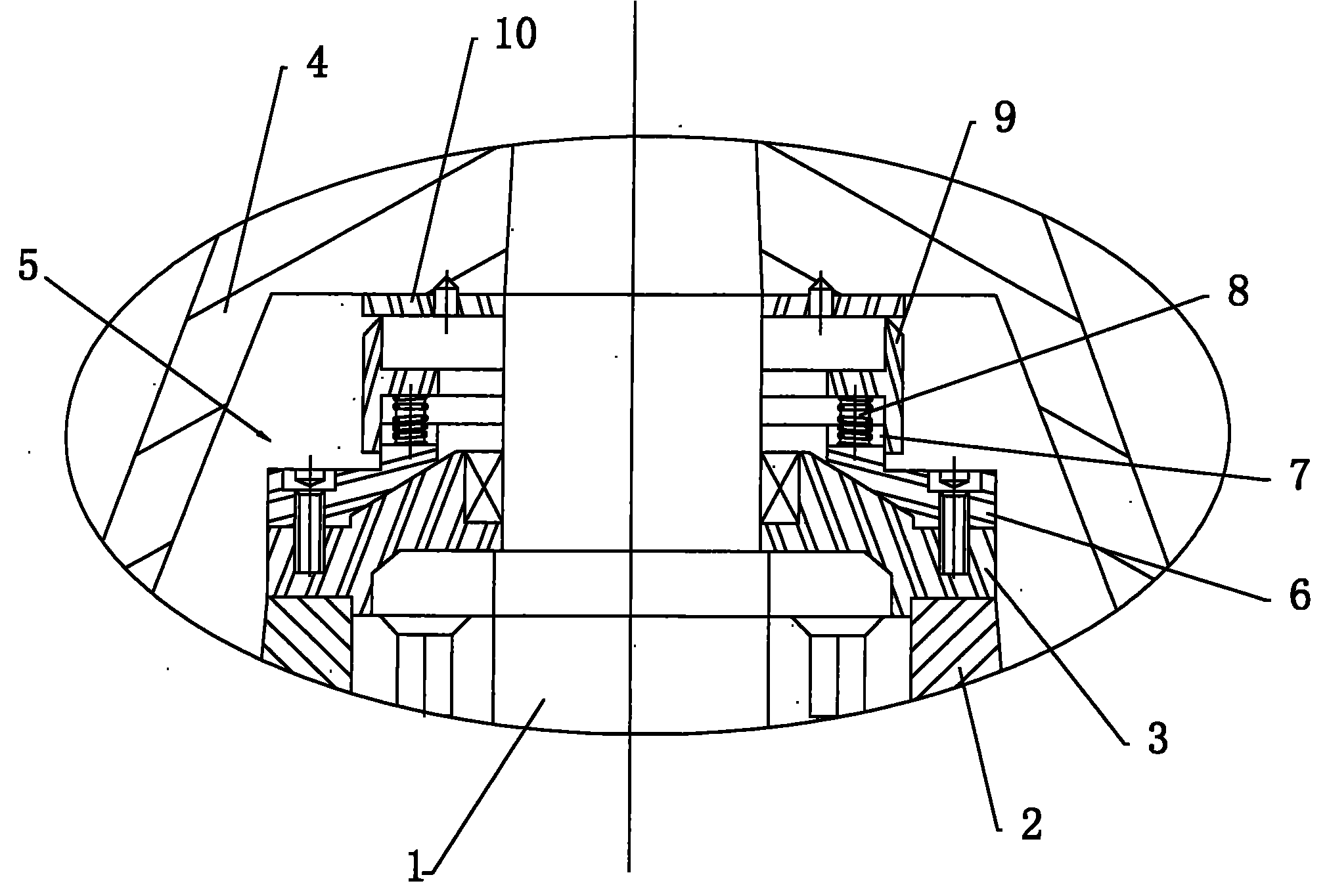
[0020] See attached figure 1 with 2 A sealing device for the main shaft of a centrifuge shown includes a main shaft 1, a bearing seat cover 3 arranged on the bearing seat 2 of the main shaft 1, a drum 4 and a sealing device for closing the bearing seat cover 3 and the rotating drum 4 The sealing part 5 between the gaps on the main shaft 1; the sealing part 5 includes a sealing base 6 fixed on the cover plate 3 of the bearing seat by bolts, a spring 8 arranged on the sealing base 6, and a spring 8 fixed on the drum 4 by screws. The upper sealing ring 10, the sealing sleeve 9 located between the sealing base 6 and the upper sealing ring 10; the sealing base 6 is arranged coaxially with the main shaft 1; the lower surface of the sealing sleeve 9 is statically sealed with the sealing base 6 through the O-shaped sealing ring 7 Cooperate, the upper surfa...
PUM
 Abstract
Description
Claims
Application Information
 - Generate Ideas
- Intellectual Property
- Life Sciences
- Materials
- Tech Scout
- Unparalleled Data Quality
- Higher Quality Content
- 60% Fewer Hallucinations
Browse by: Latest US Patents, China's latest patents, Technical Efficacy Thesaurus, Application Domain, Technology Topic, Popular Technical Reports.
© 2025 PatSnap. All rights reserved.Legal|Privacy policy|Modern Slavery Act Transparency Statement|Sitemap|About US| Contact US: help@patsnap.com