Method of removing impurity from molten steel
An inclusion and small technology, applied in the field of iron and steel metallurgy, can solve the problems such as the generation method of dispersing tiny bubbles that is not proposed, and achieve the effects of low cost, high removal efficiency, and simple and easy operation.
- Summary
- Abstract
- Description
- Claims
- Application Information
AI Technical Summary
Problems solved by technology
Method used
Image

Examples
Embodiment 1
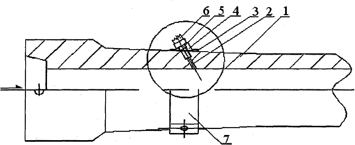
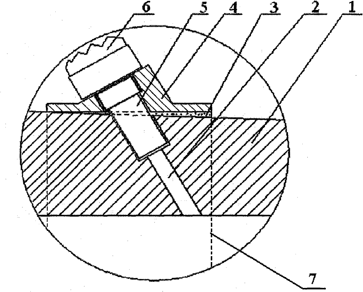
[0016] In this embodiment, the position of the through hole 2 of the shroud for metallurgy in the tundish is 100 mm from the top of the shroud, the number of the through hole 2 is 1, the diameter of the hole located on the inner wall of the shroud is 10 mm, and the length is 10 mm, and the hole located on the outer wall of the shroud The diameter is 20mm, the axial direction of the through hole and the axial direction of the upper long nozzle form an included angle of 10°, the outer diameter of the front part of the joint 5 is 20mm, and the inner diameter is 10mm.
[0017] A two-strand slab continuous casting machine is used, the section of the cast slab is 1150×230mm, and the casting speed is 1.2m / min. Argon gas is blown into the shroud through the external delivery pipe 6, the gas supply pressure is 2 atm, and the flow rate is 25 l / min. The argon gas is fully dispersed by the stream in the shroud, and a large number of dispersed micro-bubbles are generated in the tundish, an...
Embodiment 2
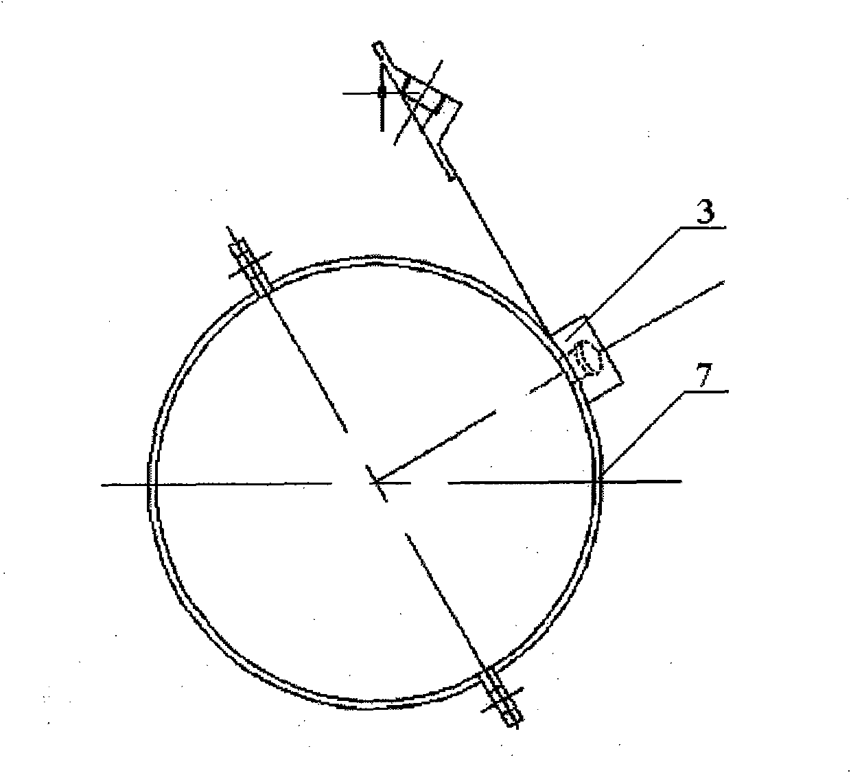
[0019] In this embodiment, the position of the through hole 2 of the shroud for metallurgy in the tundish is 160 mm from the top of the shroud, and the number of the through holes 2 is 2, distributed along the radial direction of the shroud, and the angle between the two through holes 2 is 180°. The diameter of the hole located on the inner wall of the shroud is 8 mm, and the length is 12 mm. The diameter of the hole located on the outer wall of the shroud is 30 mm. 30mm with an inner diameter of 25mm.
[0020] A two-strand slab continuous casting machine is used, the section of the cast slab is 1150×230mm, and the casting speed is 1.2m / min. Argon gas is blown into the shroud through the external delivery pipe 6, the gas supply pressure is 6 atm, and the flow rate is 300 l / min. The argon gas is fully dispersed by the stream in the shroud, and a large number of dispersed micro-bubbles are generated in the tundish, and the size of the bubbles is less than 0.8mm. The T[O] of th...
Embodiment 3
[0022] In this embodiment, the number of shroud through-holes 2 for metallurgy in the tundish is six, which are asymmetrically and arbitrarily distributed along the shroud space. The position of the uppermost through hole 2 is 80mm from the top of the long nozzle, and the position of the lowermost through hole 2 is 500mm from the top of the nozzle. The hole located on the inner wall of the shroud has a diameter of 25 mm and a length of 0 mm, and the hole located on the outer wall of the shroud has a diameter of 25 mm and a length of 60 mm. The axial direction of the through hole 2 forms an included angle of 40° with the axial direction of the upper part of the shroud, and the outer diameter of the front part of the joint 5 is 25 mm, and the inner diameter is 14 mm.
[0023] A two-strand slab continuous casting machine is used, the section of the cast slab is 1150×230mm, and the casting speed is 1.2m / min. Argon gas is blown into the shroud through the external delivery pipe 6,...
PUM
| Property | Measurement | Unit |
|---|---|---|
| Diameter | aaaaa | aaaaa |
| Length | aaaaa | aaaaa |
| Outer diameter | aaaaa | aaaaa |
Abstract
Description
Claims
Application Information
 - R&D Engineer
- R&D Manager
- IP Professional
- Industry Leading Data Capabilities
- Powerful AI technology
- Patent DNA Extraction
Browse by: Latest US Patents, China's latest patents, Technical Efficacy Thesaurus, Application Domain, Technology Topic.
© 2024 PatSnap. All rights reserved.Legal|Privacy policy|Modern Slavery Act Transparency Statement|Sitemap