
Equipment and method for treating oil extraction wastewater with integration of coalescence and hydrocyclone separation

A technology for oil extraction wastewater and cyclone separation, which is applied in centrifugal separation of water/sewage treatment, separation methods, liquid separation, etc. , the effect of reducing cost input and improving separation efficiency

Inactive Publication Date: 2011-04-20
BEIJING INSTITUTE OF PETROCHEMICAL TECHNOLOGY
View PDF7 Cites 18 Cited by
  • Summary
  • Abstract
  • Description
  • Claims
  • Application Information

AI Technical Summary

Problems solved by technology

Although this technology is simple and easy, does not require external power, and does not need to improve the original equipment, there are still some shortcomings in this in vitro series installation method. There are inevitably pipelines and valves in between, so that the oil-water mixture after the coarse-graining unit passes through these valves will still cause the particle size of the dispersed phase oil droplets to become smaller due to flow shearing, thus greatly reducing the effect of coarse-graining

Method used

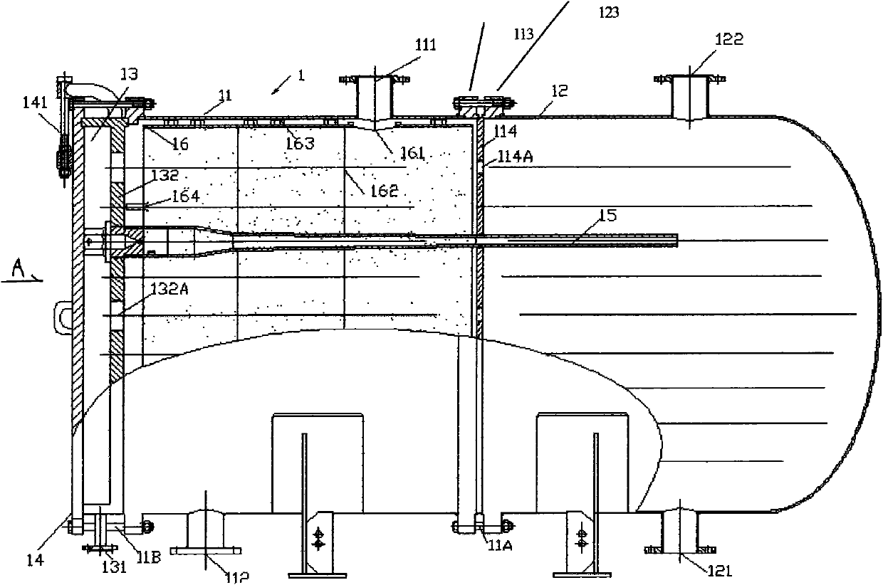

Image

  • Equipment and method for treating oil extraction wastewater with integration of coalescence and hydrocyclone separation
  • Equipment and method for treating oil extraction wastewater with integration of coalescence and hydrocyclone separation
  • Equipment and method for treating oil extraction wastewater with integration of coalescence and hydrocyclone separation

Examples


Embodiment Construction

[0026] The present invention can be implemented according to the accompanying drawings, which will be described in further detail below in conjunction with the accompanying drawings:

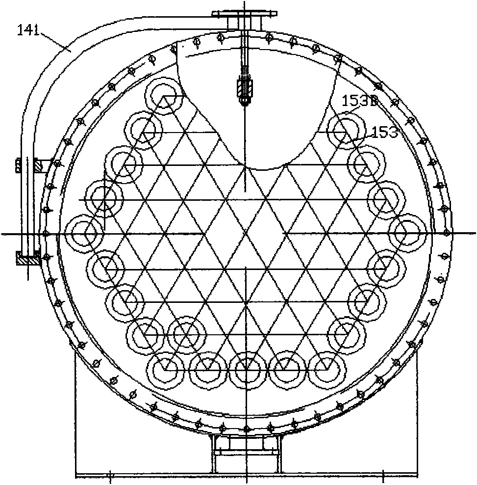
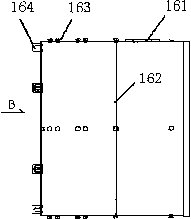
[0027] Depend on figure 1 It is shown that the coalescing and cyclone separation integrated oil production wastewater treatment equipment is mainly composed of an inlet chamber 11, an underflow chamber 12, an overflow chamber 13 and a flat head 14, wherein: the cylinder body of the inlet chamber 11 is equipped with One flange is the oil production waste water inlet 111 and the backup port 112 respectively. The inlet port 11 is also equipped with a box flange 113; Port 122, the underflow cavity 12 is also equipped with a box flange 123; the inlet cavity 11 and the underflow cavity 12 are connected and fixed through the box flanges 113, 123 and bolts 11A, and the inlet cavity 11 and the underflow cavity 12 are connected by bolts 11A The right partition 114 is clamped and fixed, and the tail of th...


PUM


Abstract

The invention relates to a piece of equipment and a method for treating oil extraction wastewater with integration of coalescence and hydrocyclone separation. The equipment mainly comprises an inlet chamber (11), an underflow chamber (12), an overflow chamber (13), and a flat seal head (14). In the inlet chamber (11) is arranged a coalescence cylinder (16) equipped with coalescence materials, and multiple assemblies of independent flow hydrocyclones (15) of each chamber are densely arranged in a hexagon manner and are transversely penetrated. The method in the invention includes the following steps: oil extraction wastewater pump is sent to an inlet of a pressure vessel, wastewater flows through the coalescence cylinder (16), small oil droplets in the dispersed phase aggregate, become larger and then enter the independent flow hydrocyclones (15) to form high-speed rotating vortex, heavy phase water is collected in the underflow chamber (12) and discharged from a water outlet (121), and light phase oil is forced to move to the axle center, flows to the top, is discharged from an overflow mouth (153D), is collected in the overflow chamber (13) and is finally discharged from an oil drain port (131). According to the method and the equipment in the invention, the size of oil droplets in the dispersed phase entering each independent flow hydrocyclone is large, so the oil-water separation efficiency is largely enhanced compared with conventional technologies and equipments. Both oil contents in the water outlet and water contents in the oil drain port are relatively low.

Description

technical field [0001] The invention relates to a method and equipment for oil and water two-phase separation, especially the integration of coalescence and cyclone separation technology, which is suitable for the purification treatment equipment and method of oil production wastewater with tiny dispersed oil droplets, and can also be used for Treatment of oily wastewater in other industries, such as the treatment of cold rolling oily wastewater and degreasing liquid in the steel industry, the discharge treatment of emulsified oil such as grinding, cutting, cooling, etc. in the machining industry, and the treatment of degreasing wastewater in the surface treatment industry, etc. Background technique [0002] In the process of petroleum development, the waste water that is separated and transferred after the degassing, dehydration, and desalination of the oil well production fluid is often called "oil production wastewater or produced water". , also contains some other impuri...

Claims


Application Information

Patent Timeline
IPC IPC(8): C02F1/38C02F1/40
Inventor 陈家庆周海周玲赵增慧俞接成
Owner BEIJING INSTITUTE OF PETROCHEMICAL TECHNOLOGY
Learn More