Integrated ion transport membrane and combustion turbine system
A technology for ion transport membranes and gas turbines, which is applied in the direction of gas turbine devices, combustion air/fuel supply, combustion chambers, etc., and can solve the problems of not publicly describing the detailed methods of integrated use
- Summary
- Abstract
- Description
- Claims
- Application Information
AI Technical Summary
Problems solved by technology
Method used
Image
Examples
Embodiment 1
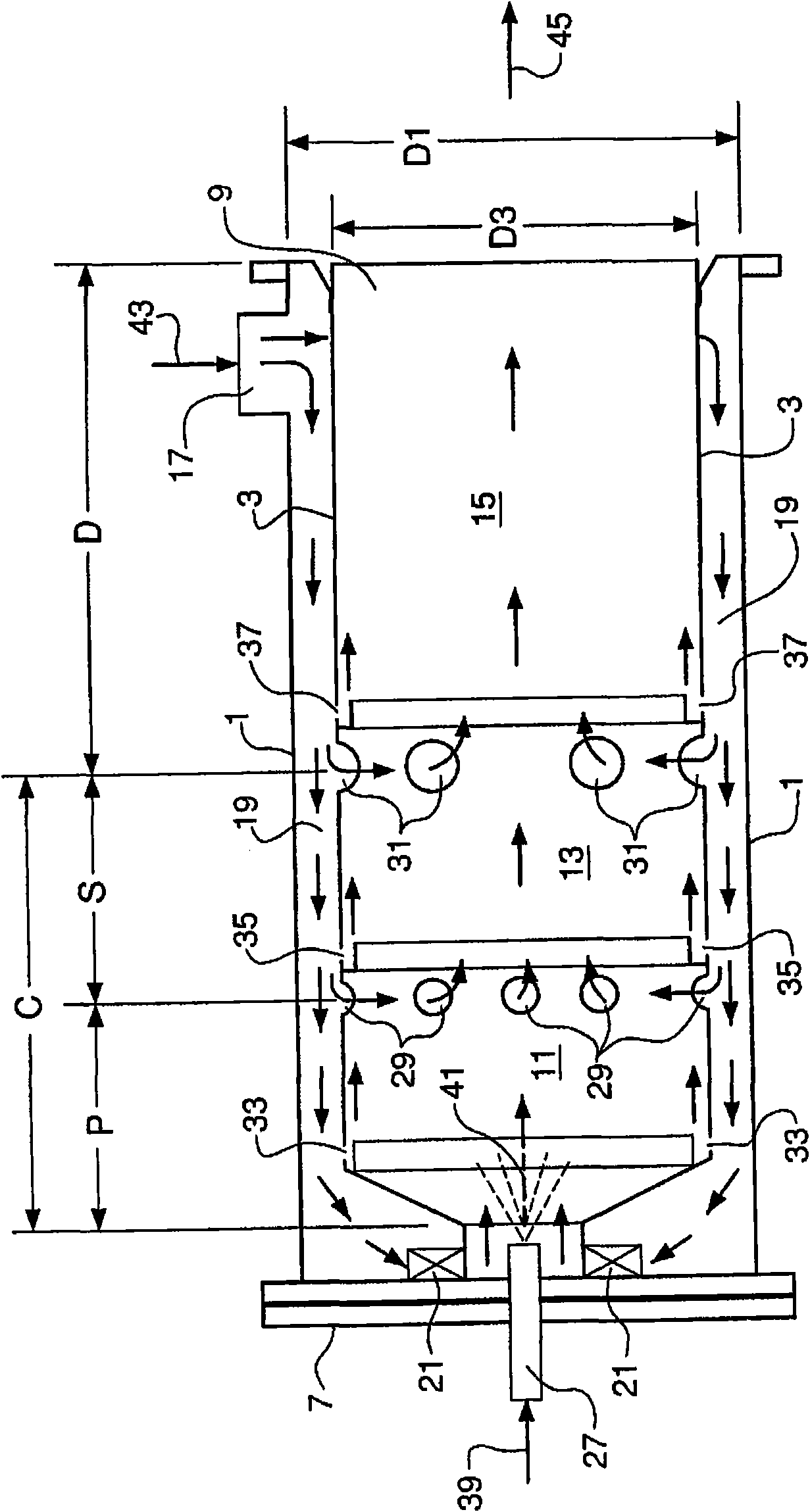
[0263] A base gas turbine engine was simulated for comparison with the integrated systems in Examples 2 to 5 presented below. A basic gas turbine not integrated with an ion transport membrane system can be removed by removing Figure 4 The combustion heater 217, the ion transport membrane system 221, the pipeline 401, the pipeline 403, the pipeline 409 and the pipeline 423 in the system are illustrated. In this basic gas turbine, the combustor 405 operates as the combustor previously described with reference to Figure 1, and runs on natural gas fuel.
[0264] Liner inlet cooling air based on 851°F (line 411, Figure 4 ) temperature and use the following engine properties:
[0265] · Compression ratio (compressor 203) = 20 / 1
[0266] · Air flow rate (compressor 203 discharge) = 344 lb / sec
[0267] ·Turbine Inlet Temperature (Turbine 257) = 2200°F
[0268] Overall air / fuel ratio = 50 / 1
[0269] · Compressor Efficiency (Compressor 203) = 85%
[0270] Turbo Efficiency (Turb...
Embodiment 2
[0274] Using the engine performance parameter simulation of embodiment 1 Figure 8 Shown is the integrated gas turbine and ion transport oxygen generation system. This baseline scenario illustrates a typical integrated gas turbine and ion transport oxygen generation system of the prior art and provides a point of reference for comparison with Examples 3-5 presented below. For this baseline example case, the amount of compressed air taken from the gas turbine compressor discharge and sent to the ion transport oxygen generation system was chosen to achieve an oxygen concentration of 14% by volume at the inlet of the power burner 805 . This oxygen concentration was chosen for the illustrative purposes of this example; other concentrations may be used in actual practice if desired.
[0275] refer to Figure 8 , at 851°F, 344 lb / sec of input air in line 201 is compressed in compressor 203 to 291 psia and split into two parts via lines 207 and 209. A first portion of compressed a...
Embodiment 3
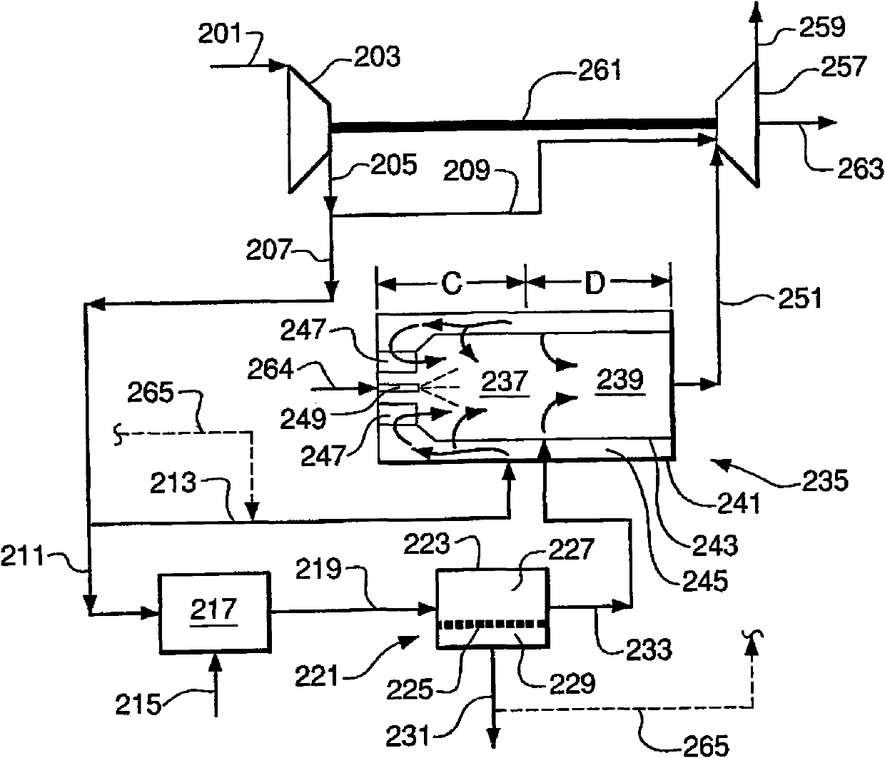
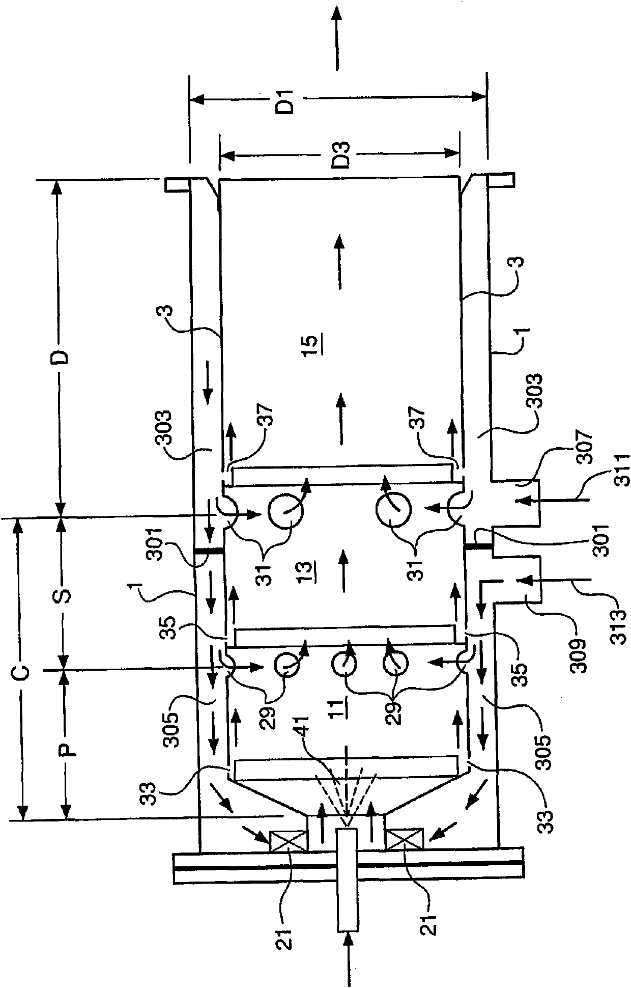
[0278] Using the engine parameters of Example 1 and image 3 The burner configuration simulation figure 2 Shown is the integrated gas turbine and ion transport oxygen generation system. The system performance achievable for this embodiment is primarily a function of splitting the airflow required for combustion and liner cooling. For conventional gas turbines, the liner cooling air flow as part of the compressor discharge typically ranges from 10% to 40%, while the amount of air required for combustion depends on how depleted the combustion process is in the primary zone ( lean) how. For Dry Low NO x combustor, a lean primary zone equivalence ratio (eg, 0.5) is necessary. The equivalence ratio, Φ, is defined as the actual fuel / air ratio divided by the stoichiometric fuel / air ratio. If another NO x Methods of control (eg, water injection), equivalence ratios as high as 1.0 in the primary zone can be used. The required corresponding combustion air as part of the compress...
PUM
 Abstract
Description
Claims
Application Information
 - R&D
- Intellectual Property
- Life Sciences
- Materials
- Tech Scout
- Unparalleled Data Quality
- Higher Quality Content
- 60% Fewer Hallucinations
Browse by: Latest US Patents, China's latest patents, Technical Efficacy Thesaurus, Application Domain, Technology Topic, Popular Technical Reports.
© 2025 PatSnap. All rights reserved.Legal|Privacy policy|Modern Slavery Act Transparency Statement|Sitemap|About US| Contact US: help@patsnap.com


