Foil type sensor with function of automatically accumulating resistance

A sensor and foil-type technology, applied in the direction of material resistance, etc., can solve the problems of long service time, structural form, complex stress conditions, and bulky bridge structure, so as to reduce production costs, facilitate large-scale applications, and improve heat resistance sexual effect

Inactive Publication Date: 2011-04-20
CENT SOUTH UNIV
View PDF4 Cites 7 Cited by
  • Summary
  • Abstract
  • Description
  • Claims
  • Application Information

AI Technical Summary

Problems solved by technology

[0016] The bridge structure is bulky, with complex structural forms and stress conditions, and has a long service life

Method used


Image

  • Foil type sensor with function of automatically accumulating resistance
  • Foil type sensor with function of automatically accumulating resistance
  • Foil type sensor with function of automatically accumulating resistance

Examples


Embodiment 1

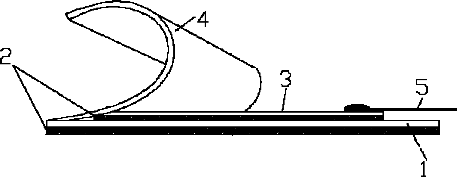
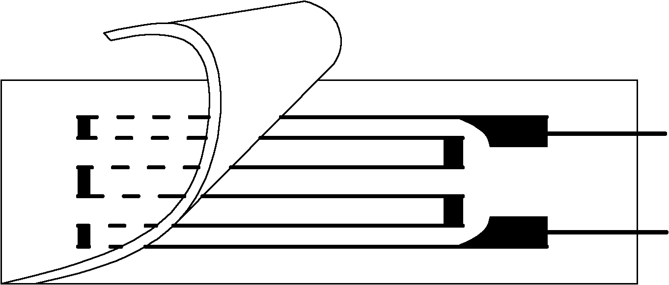
[0039] See attached figure 1 , 2 , a foil sensor with the function of automatic resistance accumulation in the present invention, comprising: a foil sensitive grid 3, a base 1, a covering layer 4, and a lead wire 5, and the foil sensitive grid 3 and the covering layer are sequentially arranged on the surface of the base 1 4. The lead wire 5 is connected to the foil-type sensitive grid 3; the foil-type sensitive grid 3 is made of copper-nickel-manganese-iron-silicon alloy foil by photochemical method according to the designed sensor structure pattern.

[0040] In this embodiment, the foil-type sensitive grid 3 is made of copper-nickel-manganese-iron-silicon precision resistance alloy, and the weight percentage of each component is:

[0041] Ni 43%, Mn 1.8%, Fe 0.1%, Si 0.3%, the balance is Cu, and its thickness is 0.005mm.

[0042] In this embodiment, the lead wire 5 is a constantan wire.

[0043] In this embodiment, the base 1 , the foil-type sensitive grid 3 and the coveri...

Embodiment 2

[0055] The product structure and preparation method prepared in this embodiment are the same as in Example 1, but the weight percentage of each component of the foil-type sensitive grid 3 is:

[0056] Ni 40%, Mn 1.4%, Fe 0.3%, Si 0.3%, the balance is Cu, and its thickness is 0.005mm.

[0057] The performance index of the foil sensor prepared in Example 2 is:

[0058] ΔR / R resistance fatigue cumulative increment: 8.075%,

[0059] Resistance cumulative strain threshold: 750με,

[0060] Temperature coefficient of resistance: 6.272×10 -6 / °C,

[0061] Gauge factor: 2.003.

Embodiment 3

[0063] The structure and preparation method of the product prepared in this embodiment are the same as in Example 1, but the weight percentage of each component of the foil-type sensitive grid 3 is:

[0064] Ni 48%, Mn 1.7%, Fe 0.2%, Si 0.3%, the balance is Cu, and its thickness is 0.005mm.

[0065] The performance index of the foil sensor prepared in Example 3 is:

[0066] ΔR / R resistance fatigue cumulative increment: 8.372%,

[0067] Resistance cumulative strain threshold: 680με,

[0068] Temperature coefficient of resistance: 6.489×10 -6 / °C,

[0069] Gauge factor: 2.057.


PUM

PropertyMeasurementUnit
gauge factoraaaaaaaaaa

Abstract

The invention relates to a foil type sensor with a function of automatically accumulating resistance. The senor comprises a foil type sensitive grid, a base, a covering layer and a lead, wherein the surface of the base is sequentially provided with the foil type sensitive grid and the covering layer, and the foil type sensitive grid is connected with the lead; and the foil type sensitive grid is made of a foil material of copper-nickel-manganese-iron-silicon alloy through a photochemical method according to the designed sensor structure. Under the effect of fatigue loading, the sensor has the function of automatically accumulating resistance, is suitable for monitoring the accumulation of fatigue damages of a bridge structure, has the capacity of temperature self-compensation and is suitable for complicated and variable climatic environments of bridge structures. The sensor has larger resistance accumulation increment and excellent fatigue service life and can be guaranteed to work for a long time without being frequently changed. The sensor also has a lower resistance accumulation strain threshold value and can be directly bonded on the surface of a structure for use. The sensor has low production cost and can be industrially applied in a large scale.

Description

technical field [0001] The invention relates to a sensor with the function of automatic accumulation of resistance under the action of fatigue load, in particular to a foil sensor with the function of automatic accumulation of resistance, which is suitable for monitoring fatigue accumulation damage of bridge structures. The invention belongs to the technical field of resistance sensors. technical background [0002] In 1966, an article reporting the study of the fatigue life meter appeared abroad, which immediately attracted great attention. In the article, Darrell R. Harting focuses on the automatic accumulation of resistance with the fatigue history-the inherent characteristics of the fatigue life meter, and also introduces the beginning and end of the discovery of this feature of the fatigue life meter: In 1959, the testing department of Boeing Aircraft Company found that Some strain gages have strange resistance growth during the fatigue loading process. Some resistance...

Claims


Application Information

Patent Timeline
Patent Type & Authority Applications(China)
IPC IPC(8): G01N27/20
Inventor 任伟新肖丹
Owner CENT SOUTH UNIV
Why Eureka
Try Eureka