
Dry method desorption device for organic waste gas activated carbon adsorption

A technology for activated carbon adsorption and organic waste gas, applied in separation methods, combustible gas purification, chemical instruments and methods, etc., can solve problems affecting desorption efficiency, increasing production costs, affecting adsorption performance, etc., and achieve the effect of avoiding the decline of adsorption capacity

Active Publication Date: 2011-04-27
曹建忠
View PDF6 Cites 16 Cited by
  • Summary
  • Abstract
  • Description
  • Claims
  • Application Information

AI Technical Summary

Problems solved by technology

Although the use of water vapor desorption has the characteristics of high phase change heat, relatively complete desorption, and easy condensation, but it also has the same disadvantages as traditional desorption: during desorption, a large amount of water vapor will condense in the adsorption layer of activated carbon. , although it has been blown by dry wind, the water content of activated carbon is still very high, which affects its adsorption performance and reduces the adsorption efficiency; in addition, the temperature of water vapor is relatively high, and if the adsorption process needs to be carried out immediately after desorption, the activated carbon will be activated at a higher temperature. The case will also affect its desorption efficiency
Therefore to overcome the above-mentioned technical problems, it is necessary to add appropriate equipment and processing technology, which increases the production cost and requires a large investment.

Method used


Image

  • Dry method desorption device for organic waste gas activated carbon adsorption
  • Dry method desorption device for organic waste gas activated carbon adsorption
  • Dry method desorption device for organic waste gas activated carbon adsorption

Examples


Embodiment Construction

[0017] The present invention will be further described below in conjunction with accompanying drawing and embodiment:

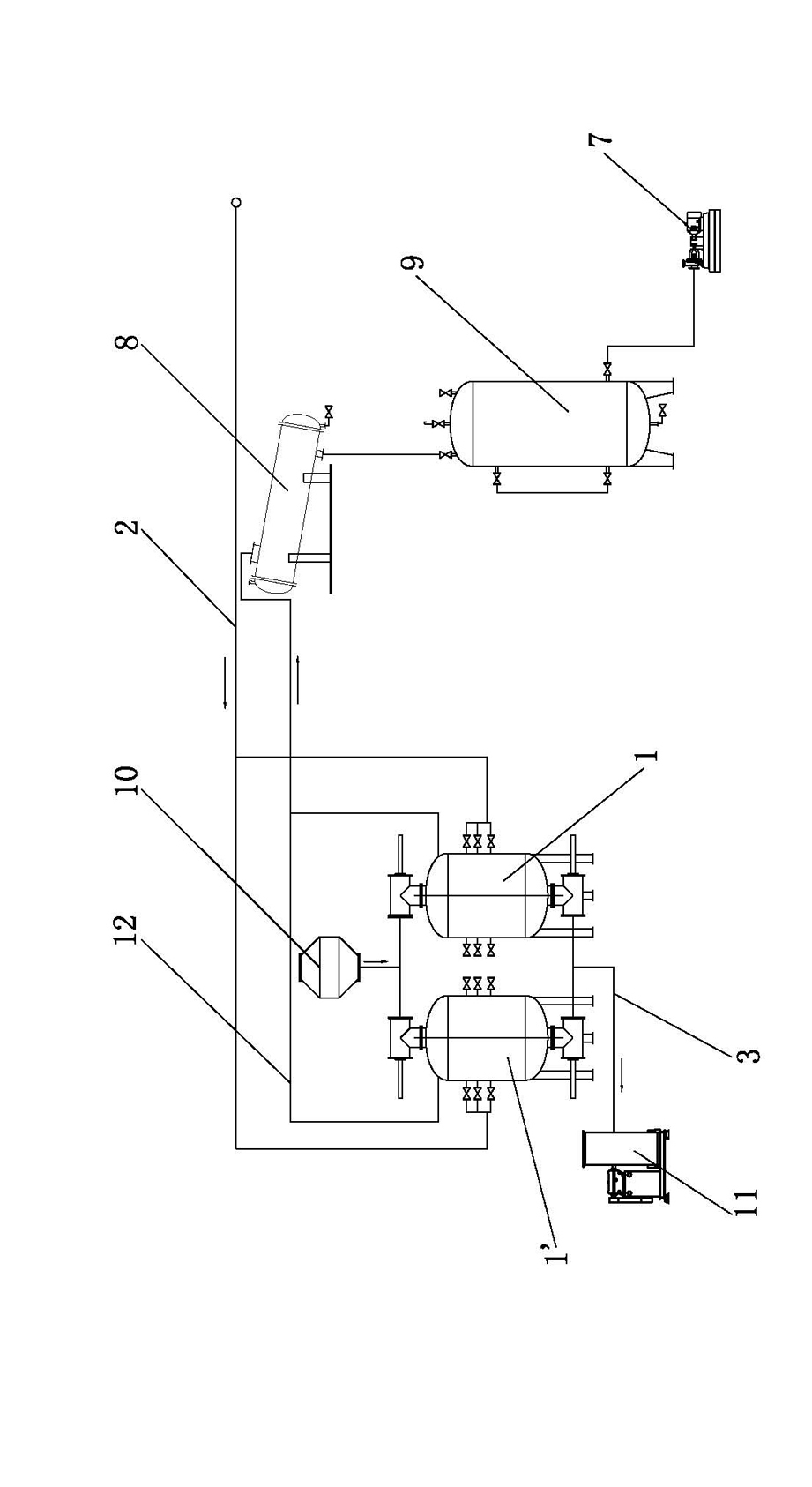
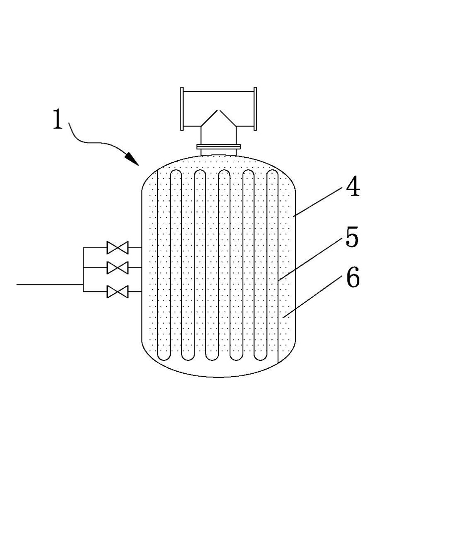
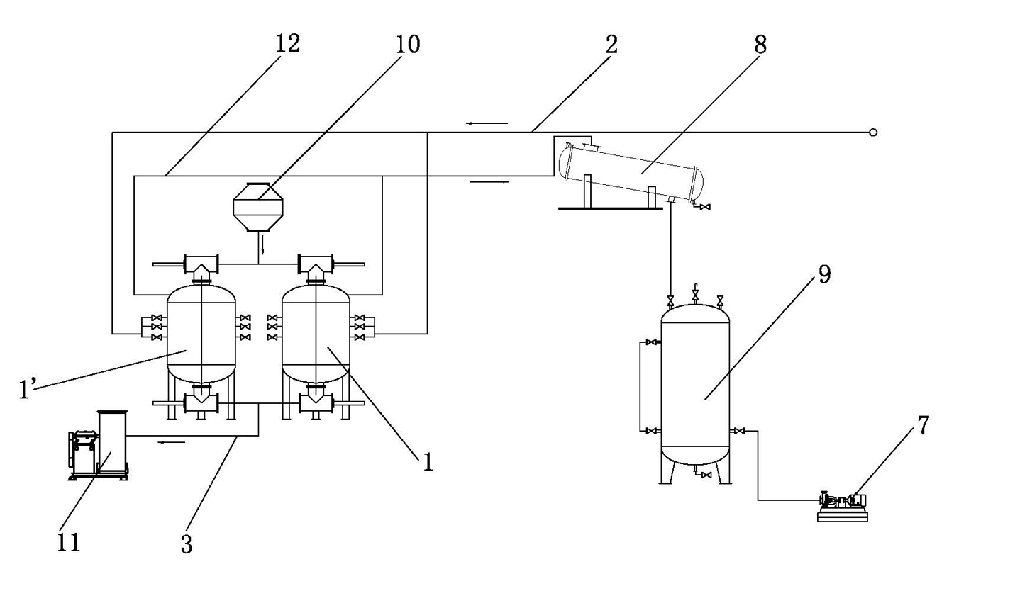
[0018] Such as figure 1 A dry-process desorption device for activated carbon adsorption of organic waste gas is shown, which includes a plurality of adsorption tanks 1 filled with activated carbon 6 arranged in parallel, a waste gas delivery channel 2 for transporting organic waste gas, and a channel for transporting purified gas. Clean gas delivery channel 3, a steam generating device for producing high-temperature desorption steam, and a solvent recovery device for collecting desorption solvent.

[0019] The exhaust gas delivery channel 2, the adsorption tank 1, and the clean gas delivery channel 3 constitute the adsorption part; the steam generating device (not shown in the figure), the adsorption tank 1 and the solvent recovery device constitute the desorption part. The adsorption tank 1 is provided with a waste gas pipe 4 for flowing through the organic...


PUM


Abstract

The invention relates to a dry method desorption device for organic waste gas activated carbon adsorption, comprising an adsorption tank filled with activated carbon, a waste gas transmission channel, a purified gas transmission channel, a steam generator and a solvent recycler, wherein the adsorption tank is internally provided with a waste gas pipe through which organic waste gas flows and a steam pipe through which desorption steam flows, the steam pipe is arranged in the waste gas pipe, activated carbon is filled in the waste gas pipe and outside the steam pipe, the recycler is also provided with a vacuum pump, and the vacuum pump vacuumizes the recycler before the desorption part operates. The invention simultaneously realizes adsorption and desorption in the same adsorption tank by virtue of two paths, the activated carbon is not directly contacted with the steam, thus maintaining the activated carbon to be dry and avoiding the problems that in the original method, steam is directly used to desorb the activated carbon so that the absorption capability of the activated carbon is reduced due to moisture absorption, and secondary pollution is caused due to emission of combined steam and solvents in the desorption process. The invention has the advantages of saving energy, avoiding pollution and reducing cost.

Description

technical field [0001] The invention relates to the field of waste gas treatment, in particular to a dry desorption device for activated carbon adsorption of organic waste gas. Background technique [0002] Activated carbon has a good specific surface area and strong adsorption, decolorization and deodorization properties, so it is often used as an adsorption medium in a circular purification system to absorb toxic and polluting substances in waste gas and wastewater. [0003] At present, the most commonly used adsorption-desorption recovery devices mainly include: air filter, adsorption tank, condenser, separator, detonator, etc. Two or more adsorption tanks are used simultaneously or alternately. The adsorption process is as follows: exhaust gas passes through the air filter to remove tiny suspended particles, then enters the top of the adsorption tank, and after being adsorbed by activated carbon in the tank, harmful components are removed, and the purified gas that meets...

Claims


Application Information

Patent Timeline
IPC IPC(8): B01J20/34B01D53/02
Inventor 曹建忠
Owner 曹建忠
Learn More