
Process nozzle and system for gasifying water coal slurry and application thereof

A process burner and coal-water slurry technology, applied in the field of coal gasification, can solve the problems of shortening the service life of the gas generator, burner erosion wear, burner abrasion, etc., and achieve the effect of effective protection and efficient cooling

Active Publication Date: 2013-11-13
CHNA ENERGY INVESTMENT CORP LTD +1
View PDF2 Cites 1 Cited by
  • Summary
  • Abstract
  • Description
  • Claims
  • Application Information

AI Technical Summary

Problems solved by technology

[0006] (1) The spraying distance of the "flame" is long, which causes severe ablation of the refractory bricks in the gasifier and shortens the service life of the gasifier;
[0007] (2) The mixing of the gasification agent and the fuel is poor, the gasification is not perfect, and the effective gas (CO+H 2 ) content of components is low, while CO 2 The content is relatively high, and the conversion rate of carbon is only 96%;
[0008] (3) The burner is severely eroded, and the service life is only 2 to 3 months
But (1) the coal slurry is a jet flow, so some coal slurry particles will still be injected into the quenching chamber without gasification and combustion, so there is still room for improvement in gasification efficiency; (2) at the same time, the burner is heated The situation of bad ablation still has limited improvement; (3) the cooling water coil is also more likely to be burned through, and even cause parking in severe cases; (4) the direct frontal impact of high-speed coal water slurry on the burner will cause the burner to burn for a long time. Abraded by erosion

Method used


Image

  • Process nozzle and system for gasifying water coal slurry and application thereof
  • Process nozzle and system for gasifying water coal slurry and application thereof
  • Process nozzle and system for gasifying water coal slurry and application thereof

Examples


Embodiment 1

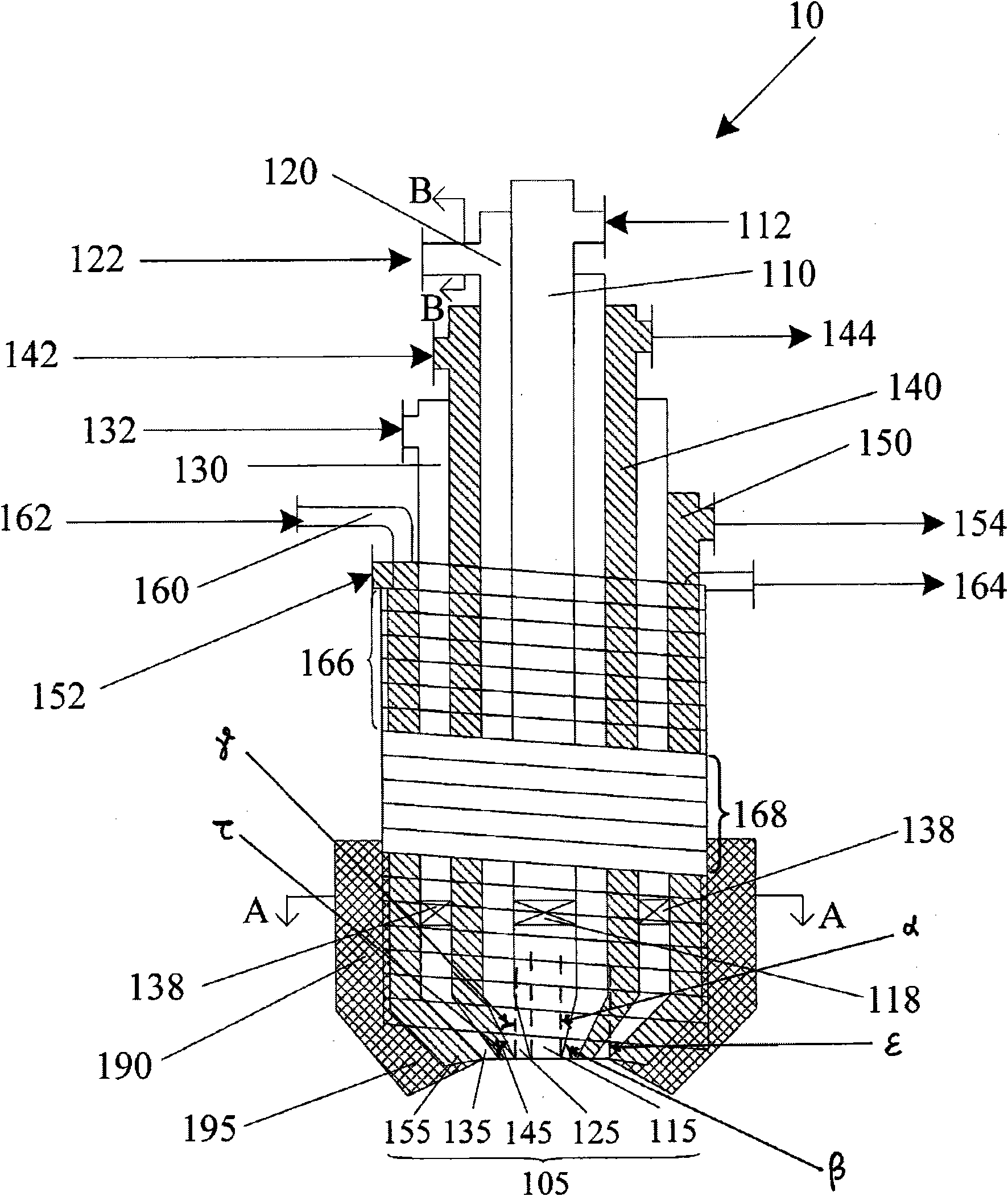
[0118] Such as figure 1 Shown, provide a kind of novel process burner 10 for coal-water slurry gasification of the present invention, specifically include:

[0119] First oxygen channel 110 (also referred to as central oxygen channel 110), this first oxygen channel includes first oxygen channel inlet 112 and first oxygen channel outlet 115; coal water slurry channel 120, this coal water slurry channel includes at least one water Coal slurry channel inlet 122 and coal water slurry channel outlet 125; The second cooling water jacket 140, this second cooling water jacket includes the second cooling water jacket inlet 142 and the second cooling water jacket outlet 144, the second The cooling water jacket 140 shrinks to the center line of the cylinder at the spout 105; the second oxygen channel 130 (also referred to as the outer epoxy channel 130), which includes the second oxygen channel inlet 132 and the second oxygen channel Exit 135.

[0120] Wherein, the first oxygen channel...

Embodiment 2

[0126] still as figure 1 As shown, the outer surface of the cooling water coil 160 of the process burner 10 in Embodiment 1 is located at the head of the process burner and is also covered with a high temperature resistant, wear and corrosion resistant shell 190, which is made of high temperature resistant, wear and corrosion resistant materials. Such as a wear-resistant ceramic layer, or using Hastenoy C-22, UMCo-50 and other materials for multiple protection, so that the process burner of the present invention is more durable.

[0127] Moreover, the cooling water coil 160 of the process burner 10 of the present invention is closely wound around the periphery of the first cooling water jacket 150 of the burner 10 , and the coils of each layer are welded together as a whole.

[0128] The burner head 105 and the cooling water coil 160 of the burner are made of materials with good wear resistance, thermal shock resistance and sulfur corrosion resistance. The burner head 105 is m...

Embodiment 3

[0163] As the process nozzle 10 of embodiment 1, wherein the pipeline at the inlet 122 of the coal-water slurry channel is as Figure 3a As shown, the pipeline at the coal-water slurry channel inlet 122 is located in the tangential direction of the coal-water slurry channel 120, so that the coal-water slurry / carbon dioxide (primary atomized coal-water slurry) enters the water along the tangential direction of the cylindrical burner 10 Coal slurry annular channel 120.

[0164] Similarly, as shown in 3b, the pipeline at the inlet 122 of the coal-water slurry channel is located in the tangential direction of the coal-water slurry channel 120 and has double inlet channels 122 .

[0165] In order to further strengthen the effect of the natural spiral flow produced by the guidance of the feed pipeline, the tangential direction pipeline located at the coal-water slurry channel 120 at the inlet 122 of the coal-water slurry channel can have a plurality of inlet channels 122, such as th...


PUM

PropertyMeasurementUnit
lengthaaaaaaaaaa

Abstract

The invention provides a process nozzle and a system for gasifying water coal slurry. The process nozzle comprises a first oxygen channel, a water coal slurry channel, a second oxygen channel, a first cooling water jacket and a cooling water coil, wherein the first oxygen channel comprises a first oxygen channel inlet and a first oxygen channel outlet; the water coal slurry channel comprises at least one water coal slurry channel inlet and a water coal slurry channel outlet; the second oxygen channel comprises a second oxygen channel inlet and a second oxygen channel outlet; the first cooling water jacket comprises a first cooling water jacket inlet and a first cooling water jacket outlet; and the cooling water coil comprises a cooling water coil inlet and a cooling water coil outlet. The process nozzle is characterized in that: the first oxygen channel is positioned at the central position of the process nozzle; the water coal slurry channel is positioned between the first oxygen channel and the second oxygen channel and surrounds the periphery of the first oxygen channel; and the second oxygen channel surrounds the periphery of the water coal slurry channel. The process nozzle reduces the length of combustion flame more effectively, reduces the ablation of flame on a refractory brick, promotes the mixing and atomization of water coal slurry and oxygen and improves gasification efficiency.

Description

technical field [0001] The invention relates to the field of coal gasification, in particular to a process burner and system for coal-water slurry gasification and its application. Background technique [0002] Coal is an important energy source. For a long time, the use of coal has been accompanied by serious environmental pollution. In recent years, people have paid more and more attention to clean coal technology aimed at reducing pollution emissions and improving utilization efficiency; coal gasification technology, as one of the coal processing and conversion technologies, is considered to be one of the most efficient and clean clean coal technologies. Modern coal gasification technology, especially high-pressure, large-capacity entrained-bed gasification technology has been widely used in industry, and Texaco coal-water slurry pressurized gasification technology is the most typical representative. In my country, many manufacturers have introduced and used Texaco techn...

Claims


Application Information

Patent Timeline
Patent Type & Authority Patents(China)
IPC IPC(8): B05B7/08C10J3/50C10J3/48
Inventor 唐煜朱平王家信徐祖斌暴秋霖杜迎春胡先君汤中文李海宾兰秀菊张永胜罗泽林薛振欣付君刘柱元
Owner CHNA ENERGY INVESTMENT CORP LTD
Learn More