Variable damping absorber

A shock absorber and damping technology, applied in shock absorbers, liquid shock absorbers, shock absorbers, etc., can solve problems such as short life, difficult manufacturing, and easy precipitation of magnetorheological fluids

Inactive Publication Date: 2011-04-27
CHONGQING UNIV
View PDF9 Cites 19 Cited by
  • Summary
  • Abstract
  • Description
  • Claims
  • Application Information

AI Technical Summary

Problems solved by technology

Domestically, there have been patent applications for variable (or adjustable) damping shock absorbers that can adapt to different roads and usage conditions. For example, the application number is 91201256.0, which discloses an adjustable damping shock absorber, but this patent will stepper motors It is installed in the dust cover, which requires a large installation space. The stepper motor is placed in a vibrating environment for a long time, and its life is short, and the hollow piston rod is used, which is difficult to manufacture and has low mechanical strength.
Another example is that the application number is 99217931.9, which announces a built-in solenoid valve type three-stage adjustable damping shock absorber. In this patent, the solenoid valve is placed horizontally in the middle of the piston, so that the installation space is relatively large, and the hollow piston rod is adopted. Its manufacturing More difficult, low mechanical strength, and its piston structure is more complicated, and the manufacturing cost is relatively high
There is also the magneto-rheological intelligent shock absorber for miniature cars announced as applic...

Method used


Image

  • Variable damping absorber
  • Variable damping absorber
  • Variable damping absorber

Examples


Embodiment Construction

[0017] The present invention will be further described below in conjunction with the accompanying drawings and specific examples.

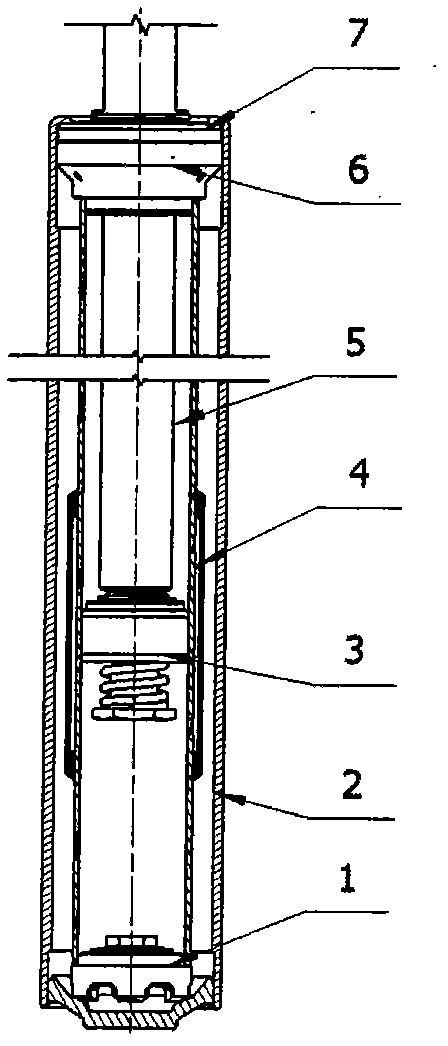
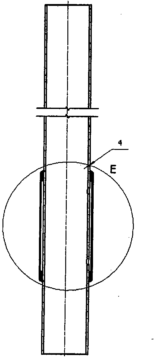
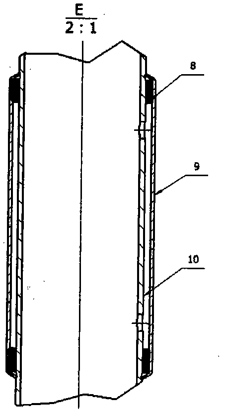
[0018] The variable damping shock absorber involved in the present invention achieves the purpose of changing the damping force of the shock absorber by changing the effective area of ​​the orifice through which the oil liquid of the shock absorber flows. The variable damping shock absorber such as figure 1 Shown is based on the existing double-tube hydraulic shock absorber, drill 1 to 4 pairs of round holes with different center distances on the working cylinder wall along the direction of its generatrix. The balance position of the holes is the vibration reduction under the rated load of the vehicle. The equilibrium position of the piston of the device. Such as figure 2 and image 3 As shown, the size of the hole drilled on the working cylinder is Φ1.0~3.0mm, the hole center distance is 25~60mm, and the hole is separated from the environment...


PUM


Abstract

The invention relates to a variable damping absorber. In the variable damping absorber, circular holes with specified numbers, positions and sizes are drilled on the working cylinder wall of an ordinary dual-cylindrical hydraulic absorber for the conventional passive suspension and are separated from environment outside the working cylinder, and the area of a channel through which oil in the absorber flows in the working process under different working conditions is changed to fulfill the aim of changing the damping force of recover stroke and compression stroke. Bench tests and loading road tests prove that the absorber has the excellent performance and stable damping characteristic. According to the condition of the machined holes, the absorber can produce 2 to 5 levels of damping force, and once the absorber is designed, the damping force can be provided automatically according to the vibrating amplitude of vehicle bodies without arranging a damp regulating mechanism and a control mechanism additionally, so the absorber has a simple structure and low cost, is easy to manufacture, and has the high practical value. The variable damping absorber can be applied to semiactive suspension systems, seats of drivers and vibration isolation and vibration attenuation of driving cabs in various vehicles.

Description

technical field [0001] The invention belongs to a vehicle shock absorber, in particular to a variable damping shock absorber. Background technique [0002] Shock absorber is an important part of the car, and its performance directly affects the comfort, handling stability and safety of the car. At present, all kinds of domestic cars, including imported technology or various types of cars produced by Sino-foreign joint ventures, such as Santana, Audi, Fukang, Buick, etc., basically use traditional shock absorbers with invariable damping, so it is difficult to adapt to different roads. and usage status. Domestically, there have been patent applications for variable (or adjustable) damping shock absorbers that can adapt to different roads and usage conditions. For example, the application number is 91201256.0, which discloses an adjustable damping shock absorber, but this patent will stepper motors It is installed in the dust cover, so that the required installation space is ...

Claims


Application Information

Patent Timeline
IPC IPC(8): F16F9/19F16F9/48
Inventor 徐中明李仕生贺岩松张志飞
Owner CHONGQING UNIV
Why Eureka
Try Eureka