
Large-torque hydraulic electrogenerating speed change device

A speed change device and high-torque technology, which is applied in the field of high-torque hydroelectric power generation speed change devices, can solve problems such as the unreasonable meshing of the oil-sprayed spherical top lubricated internal gear sleeves, and achieve the effects of light weight, good rigidity, and improved load-carrying capacity

Inactive Publication Date: 2013-05-01
SHAOXING YOURUN ELECTRAND MACHINE CO LTD
View PDF5 Cites 1 Cited by
  • Summary
  • Abstract
  • Description
  • Claims
  • Application Information

AI Technical Summary

Problems solved by technology

[0003] (A) It is unreasonable to lubricate the meshing part of the inner gear sleeve with the oil injection ball top, because the inner gear sleeve is a kind of coupling with only a slight relative rotation. On the other hand, the inner gear sleeve is in the high-speed area, and the oil splashed by the transmission part enough to lubricate

Method used


Image

  • Large-torque hydraulic electrogenerating speed change device
  • Large-torque hydraulic electrogenerating speed change device

Examples


Embodiment Construction

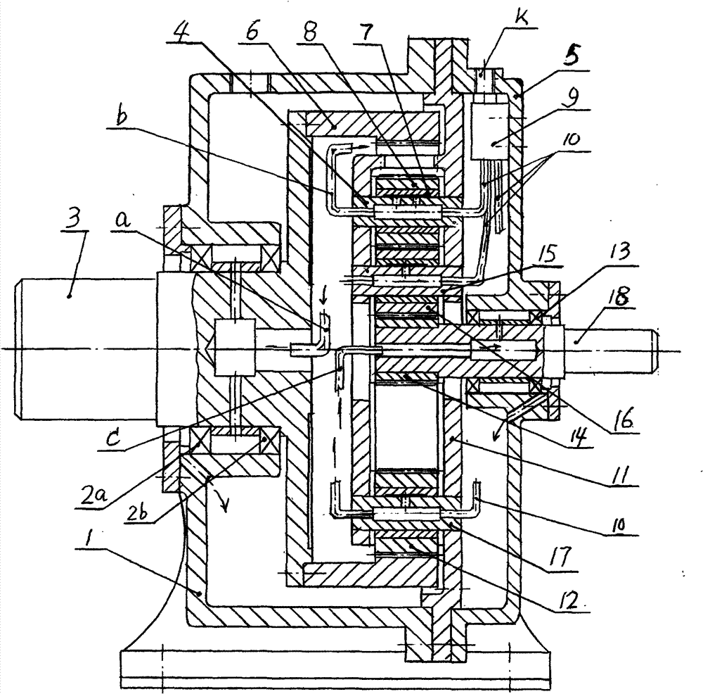
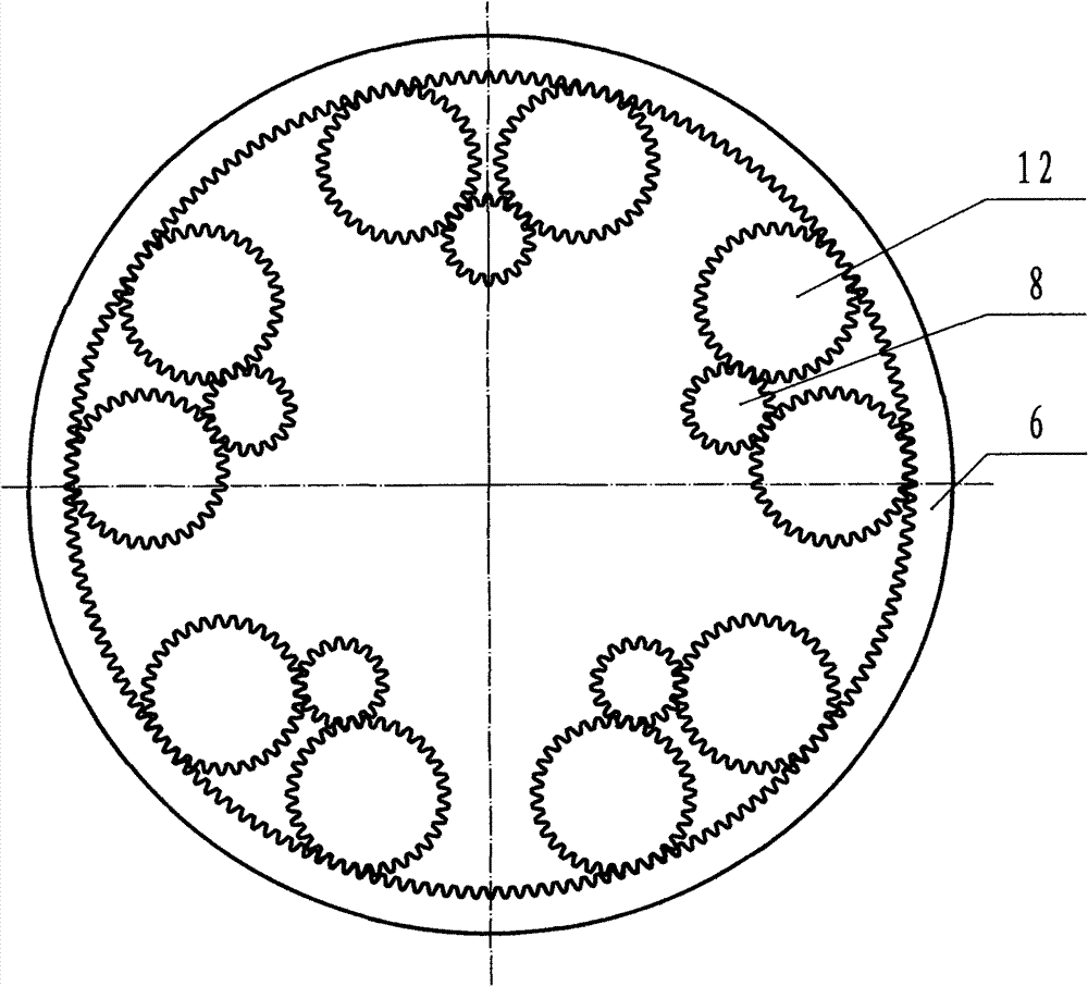
[0015] see figure 1 .and 2. a high-torque hydroelectric power transmission device, comprising a base 1, a high-speed shaft 18, two first support bearings 13, a sun gear 14 mounted on the high-speed shaft 18, and 3-5 evenly distributed quasi-planets Wheel 8, sliding bearing 7, hollow planetary wheel shaft 4, large end cover 5, fixed frame 11, inner ring gear (6), two second supporting bearings (2a, 2b) of low-speed shaft 3, large end cover 5 and The fixed frame 11 and the input end face of the frame 1 are connected, and the hollow planetary wheel shaft 4 is fixed on the frame 11, and the input from the low-speed shaft and the inner ring gear 6 to the output of the sun gear 14 and the high-speed shaft 18 is a single-stage speed increase. There is an intermediate wheel 16 between the sun gear 14 and the uniformly distributed 3-5 quasi-planetary gears 8, and the mandrel 15 of the intermediate wheel is fixed on the frame 11. Two identical splitter gears 12 arranged symmetrically o...


PUM


Abstract

The invention relates to the technical field of speed increase in speed change drive, in particular to a large-torque hydraulic electrogenerating speed change device comprising a high-speed shaft, a sun gear, 3-5 quasi planet gears, an idle gear, planetary gear shafts, a large end shaft, a fixed bracket, an inner gear, a shunt gear, a low-speed shaft and a machine seat, wherein the large end cover is sequentially connected with the fixed bracket and the end face of the input end of the machine seat; and the planetary gear shafts are fixed on the bracket. The large-torque hydraulic electrogenerating speed change device is characterized in that: (A) the large end cover is provided with an oil feed screw hole K; one end of the screw hole is connected with a thin hole station; the other end of the screw hole is connected with a lubricating hole distributor and three oil outlet pipes of the distributor are respectively connected to one end of each planetary gear shaft; (B) the other ends of the three planetary gear shafts are connected with oil pipes a, b and c which respectively point to the meshed parts of a low-speed shaft blind hole, an inner gear and a planet gear and a high-speedshaft blind hole; and (C) a main body of the machine seat is a casting thin-wall integral cylinder. The invention has the benefits that: (a) the resistance coefficient zeta of a lubricating system issmall; (b) the integral casing cylinder machine seat is free from being detached during maintenance, so that the large-torque hydraulic electrogenerating speed change device has the advantages of high mechanical strength, favorable rigidity, light weight, favorable technical performance, small thickness, reasonable stress distribution and suitability for production in batch; and (c) the power is shunt when reaching 6-10, so that the bearing capacity is improved by 1-2 times and the volume is reduced by 35-45 percent.

Description

【Technical field】 [0001] The invention relates to the technical field of speed-up in variable-speed transmission, and relates to a high-torque hydroelectric power generation speed change device. 【Background technique】 [0002] The invention patent "Hydraulic Power Generation Transmission Device" (ZL200810022394) belongs to the NGW planetary transmission, and obtained the invention patent right due to the following two improvements: (1) Introducing an "oil injection dome" to lubricate the meshing part of the inner gear sleeve; (2) ) In order to facilitate disassembly and assembly during maintenance, the traditional integral cylindrical frame of the planetary gearbox is changed to a split welded frame. The main problems are: [0003] (A) It is unreasonable to lubricate the meshing part of the inner gear sleeve with the oil injection ball top, because the inner gear sleeve is a kind of coupling with only a slight relative rotation. On the other hand, the inner gear sleeve is in...

Claims


Application Information

Patent Timeline
Patent Type & Authority Patents(China)
IPC IPC(8): F16H57/08F16H57/04
CPCF16H57/0479
Inventor 吴声震
Owner SHAOXING YOURUN ELECTRAND MACHINE CO LTD
Learn More