Method for manufacturing micromechanical shutter

A manufacturing method and blinds technology, which are applied in the direction of optomechanical equipment, patterned surface photolithography, microstructure technology, etc., can solve the problems of difficult blinds structural materials, low fatigue strength, low reliability, etc., and achieve good results. Space environment adaptability, low cost, effect of improving performance and function

Active Publication Date: 2011-04-27
NO 510 INST THE FIFTH RES INST OFCHINA AEROSPAE SCI & TECH
View PDF6 Cites 2 Cited by
  • Summary
  • Abstract
  • Description
  • Claims
  • Application Information

AI Technical Summary

Problems solved by technology

The patent (Patent No. US6226116) proposes a micromechanical shutter. Since silicon is used as a structural material for this micromechanical shutter, silicon is a brittle material. Many shortcomings such as low fatigue strength, short life and low reliability
However, the existing louver manufacturing method is usually silicon-based integrated circuit processing technology, which makes it difficult to use other materials as the structural material of the louver

Method used


Image

  • Method for manufacturing micromechanical shutter
  • Method for manufacturing micromechanical shutter
  • Method for manufacturing micromechanical shutter

Examples


specific Embodiment 1

[0032] 1. Select a stainless steel substrate with a size of 50mm×50mm×0.8mm, soak it in dilute nitric acid for 15 minutes to remove the oxide on the surface of the stainless steel sheet, then soak it in concentrated alkali solution for 20 minutes to remove the oil on the surface of the stainless steel sheet, and finally use it Dry in deionized water after cleaning;

[0033] 2. On the upper and lower surfaces of the stainless steel substrate processed in step 1, prepare a layer of positive SU-8 photoresist by spraying method, and pre-cure the photoresist for 30 minutes at 85 degrees Celsius;

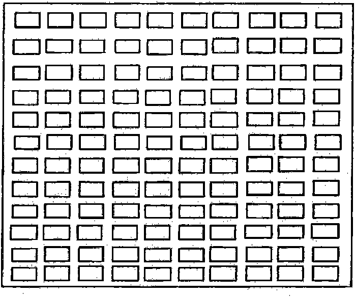
[0034] 3. On the photoresist on the upper surface after pre-curing prepared in step 2, use a rectangular hole array as a mask, and expose it under an exposure machine, wherein the overall size of the mask is as large as that of the stainless steel substrate, and the size of the rectangular hole is 2mm×1mm, spacing 0.2mm;

[0035] 4. Soak the substrate in the photoresist developer for 5 m...

Embodiment 2

[0049] 1. Select a stainless steel substrate with a size of 50mm×50mm×0.6mm, soak it in dilute nitric acid for 15 minutes to remove the oxide on the surface of the stainless steel sheet, then soak it in concentrated alkali solution for 20 minutes to remove the oil on the surface of the stainless steel sheet, and finally use it Drying after washing with ionized water;

[0050] 2. On the upper and lower surfaces of the stainless steel substrate processed in step 1, prepare a layer of positive SU-8 photoresist by spraying method, and pre-cure the photoresist for 30 minutes at 85 degrees Celsius;

[0051] 3. On the photoresist on the upper surface after pre-curing prepared in step 2, use a rectangular hole array as a mask, and expose it under an exposure machine, wherein the overall size of the mask is as large as that of the stainless steel substrate, and the size of the rectangular hole is 1.6mm×0.7mm, spacing 0.2mm;

[0052] 4. Soak the substrate in the photoresist developer f...

Embodiment 3

[0066] 1. Select a stainless steel substrate with a size of 45mm×45mm×0.7mm, soak it in dilute nitric acid for 15 minutes to remove the oxide on the surface of the stainless steel sheet, then soak it in concentrated alkali solution for 20 minutes to remove the oil on the surface of the stainless steel sheet, and finally use it Drying after washing with ionized water;

[0067] 2. On the upper and lower surfaces of the stainless steel substrate processed in step 1, prepare a layer of positive SU-8 photoresist by spraying method, and pre-cure the photoresist for 30 minutes at 85 degrees Celsius;

[0068] 3. On the photoresist on the upper surface after pre-curing prepared in step 2, use a rectangular hole array as a mask, and expose it under an exposure machine, wherein the overall size of the mask is as large as that of the stainless steel substrate, and the size of the rectangular hole is 1.8mm×0.8mm, spacing 0.2mm;

[0069] 4. Soak the substrate in the photoresist developer f...


PUM

PropertyMeasurementUnit
Thicknessaaaaaaaaaa
Thicknessaaaaaaaaaa

Abstract

The invention relates to a method for manufacturing a micromechanical shutter, which comprises the following steps of: 1) selecting a stainless steel substrate, preparing a layer of positive photoresist on the upper and lower surfaces of the substrate respectively, and pre-curing the photoresist; 2) exposing a rectangular hole array serving as a mask, wherein the pre-cured photoresist on the lower surface is not exposed; 3) developing the substrate, finishing full curing of the photoresist, then performing corrosion, removing the photoresist and cleaning the substrate; 4) spraying the positive photoresist on the upper and lower surfaces of the substrate, and pre-curing the photoresist; 5) on the photoresist on the lower surface of the substrate, exposing a twist beam type shutter corroding pattern array serving as a mask, wherein the upper surface of the substrate is not exposed; 6) developing the substrate, finishing full curing of the photoresist, then performing corrosion, removing the photoresist and cleaning the substrate; 7) manufacturing a shutter substrate; and 8) assembling and fixing the shutter blade structure and the substrate, and finishing upper and lower electrode leads. According to the method, the stainless steel is used as a structural material, so the micromechanical shutter has longer service life and higher reliability.

Description

technical field [0001] The invention relates to a manufacturing method of a micromechanical shutter, in particular to a manufacturing method of a micromechanical shutter which is used for satellite active thermal control and uses stainless steel as the main structural material. Background technique [0002] Micromechanical louvers have an urgent application demand in the field of spacecraft thermal control. Its main structure is a micro window that can be opened and closed. The micro window is controlled by adjusting the on-off and size of the voltage applied between the micro window and the substrate The opening and closing angle is equivalent to adjusting the size of the cooling surface, thus realizing the active thermal control of the spacecraft. The patent (Patent No. US6226116) proposes a micromechanical shutter. Since silicon is used as a structural material for this micromechanical shutter, silicon is a brittle material. There are many shortcomings such as low fatigu...

Claims


Application Information

Patent Timeline
IPC IPC(8): G03F7/00B81C1/00
Inventor 曹生珠陈学康吴敢杨建平王瑞尚凯文王兰喜王晓毅韦波
Owner NO 510 INST THE FIFTH RES INST OFCHINA AEROSPAE SCI & TECH
Why Eureka
Try Eureka