Electronic ballast for setting and adjusting output power in fixed time via dial-up

An electronic ballast and output power technology, applied in electric light sources, lighting devices, electrical components, etc., can solve the problems of ballast performance, life, stability effects, poor stability and reliability, and high circuit output power. , to save power consumption, prolong lamp life, and avoid audio resonance.

Inactive Publication Date: 2011-04-27
NANJING JISHAN LIGHTING TECH
View PDF5 Cites 7 Cited by
  • Summary
  • Abstract
  • Description
  • Claims
  • Application Information

AI Technical Summary

Problems solved by technology

However, traditional electronic ballasts have disadvantages such as large volume, complex circuit, high energy consumption, high cost, poor stability and reliability, etc.
At the same time, the electronic ballasts in the prior art do not have the function of setting and regularly adjusting the output power, which results in that when the voltage of the power grid is low, the generated light is very dark, and normal lighting cannot be performed; when the voltage of the power grid is high, The output power of the circuit is very large, which reduces the service life of the ceramic metal halide lamp
This will also have a great impact on the performance, life and stability of the ballast

Method used


Image

  • Electronic ballast for setting and adjusting output power in fixed time via dial-up
  • Electronic ballast for setting and adjusting output power in fixed time via dial-up
  • Electronic ballast for setting and adjusting output power in fixed time via dial-up

Examples


Embodiment Construction

[0024] The present invention will be further described below in conjunction with the accompanying drawings.

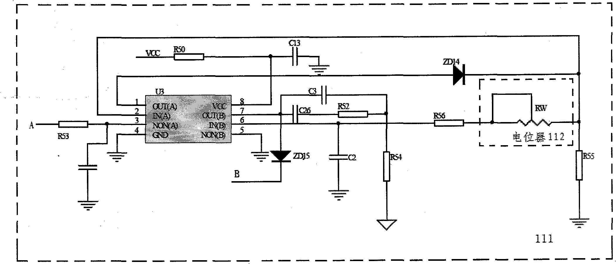
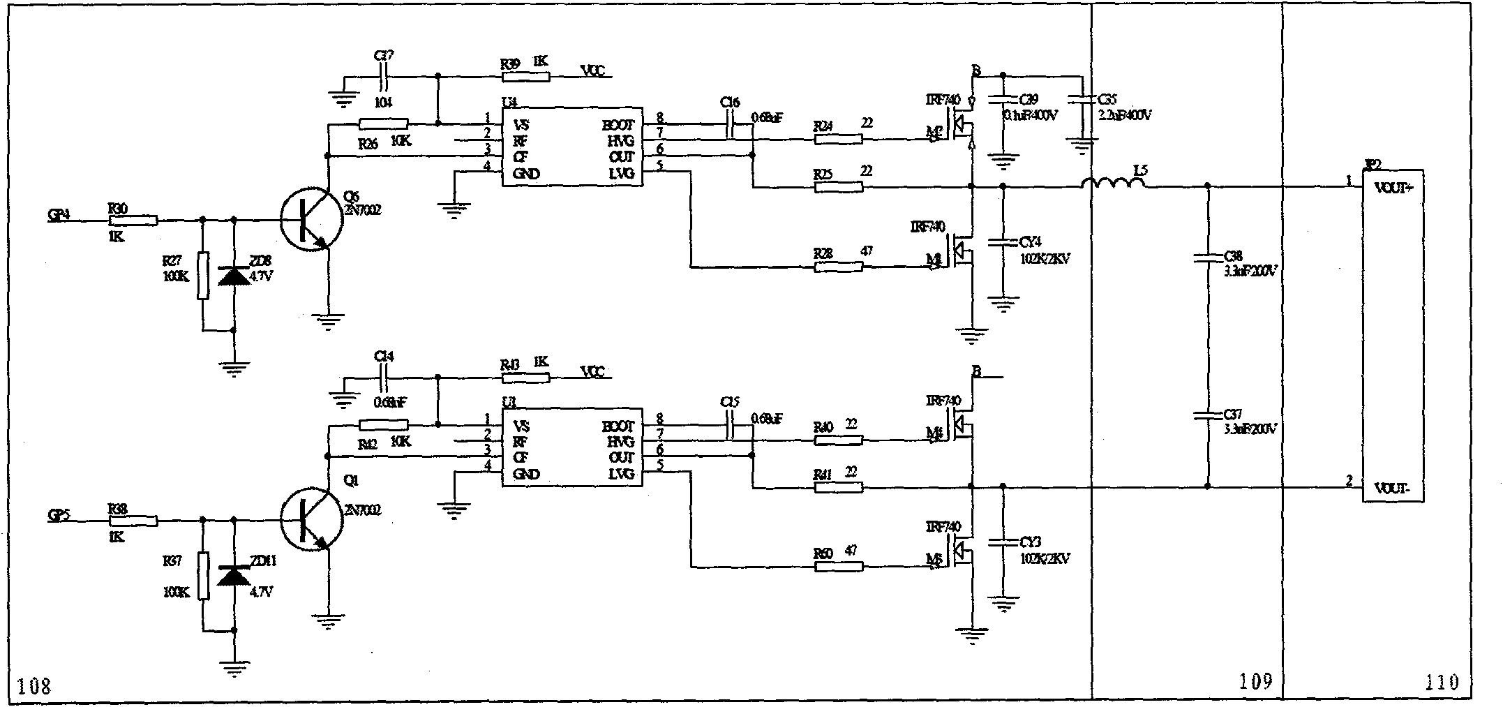
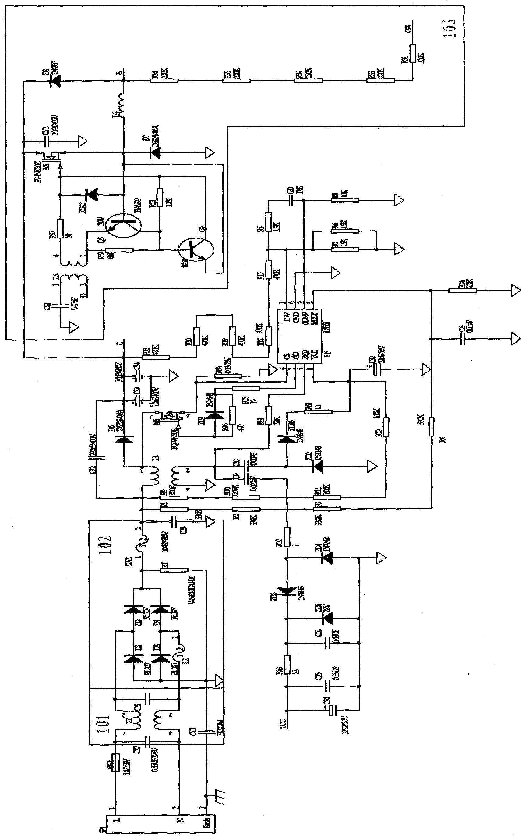
[0025] Such as figure 1 According to the present invention, the electronic ballast for adjusting the output power regularly by dialing the code includes: EMI filter circuit 101, bridge rectifier and PFC circuit 102, step-down switch circuit 103, dial switch 104, single-chip microcomputer circuit 105, PWM control circuit 106, A full bridge drive circuit 107 , a full bridge inverter circuit 108 and a resonant ignition circuit 109 . The dial switch 104, single-chip microcomputer circuit 105, PWM control circuit 106, step-down switch circuit 103, full-bridge inverter circuit 108, resonant ignition circuit 109 and ceramic metal halide lamp 110 are connected in sequence, and the EMI filter circuit 101, bridge Type rectification and PFC circuit 102 and step-down switch circuit 103 are connected successively, and described potentiometer 112, comparator 111 and PWM control cir...


PUM


Abstract

The invention discloses an electronic ballast for setting and adjusting output power in fixed time via dial-up, belonging to the technical field of electronic ballasts. The electronic ballast comprises an EMI (Electro-Magnetic Interference) filter circuit, a bridge type rectification and PFC (Power Factor Correction) circuit, a step-down switch circuit, a dial-up switch, a single chip circuit, a PWM (Pulse-Width Modulation) control circuit, a full-bridge driving circuit, a full-bridge inverter circuit and a resonant ignition circuit, wherein the dial-up switch, the single chip circuit, the PWM control circuit, the step-down switch circuit, the full-bridge inverter circuit and the resonant ignition circuit are connected sequentially; the EMI filter circuit, the bridge type rectification and PFC circuit and the step-down switch circuit are connected sequentially; the full-bridge driving circuit is respectively connected with the single chip circuit and the full-bridge inverter circuit; and the step-down switch circuit is further connected with the single chip circuit. The electronic ballast has simple structure, small volume and low energy consumption, can conveniently set the output power and adjust the output power in fixed time, and is suitable for being used as an electronic ballast of a ceramic metal halide.

Description

technical field [0001] The invention relates to an electronic ballast, in particular to an electronic ballast for a metal halide lamp. Background technique [0002] As a new type of energy-saving light source, ceramic metal halide lamps have been widely used because of their high luminous efficiency, good color rendering, and long life. Ceramic metal halide lamps need to be used in conjunction with electronic ballasts with excellent performance, and the requirements for the start-up process and timing control of electronic ballasts for ceramic metal halide lamps are relatively high. However, traditional electronic ballasts have disadvantages such as large volume, complex circuit, high energy consumption, high cost, poor stability and reliability, etc. At the same time, the electronic ballasts in the prior art do not have the function of setting and regularly adjusting the output power, which results in that when the voltage of the power grid is low, the generated light is v...

Claims


Application Information

Patent Timeline
Patent Type & Authority Applications(China)
IPC IPC(8): H05B41/282H05B41/392
Inventor 洪春旭李自强
Owner NANJING JISHAN LIGHTING TECH
Why Eureka
Try Eureka