Plasma processing apparatus

A processing device, plasma technology, applied in the direction of plasma, gaseous chemical plating, coating, etc., can solve the problems of mutual interference, unstable discharge, etc.

Inactive Publication Date: 2011-04-27
SHARP KK
View PDF2 Cites 5 Cited by
  • Summary
  • Abstract
  • Description
  • Claims
  • Application Information

AI Technical Summary

Problems solved by technology

However, since the plasma discharge itself cannot be suppressed, and mutual interference between adjacent plasmas occurs, the discharge is very unstable

Method used


Image

  • Plasma processing apparatus
  • Plasma processing apparatus
  • Plasma processing apparatus

Examples


Embodiment approach 1

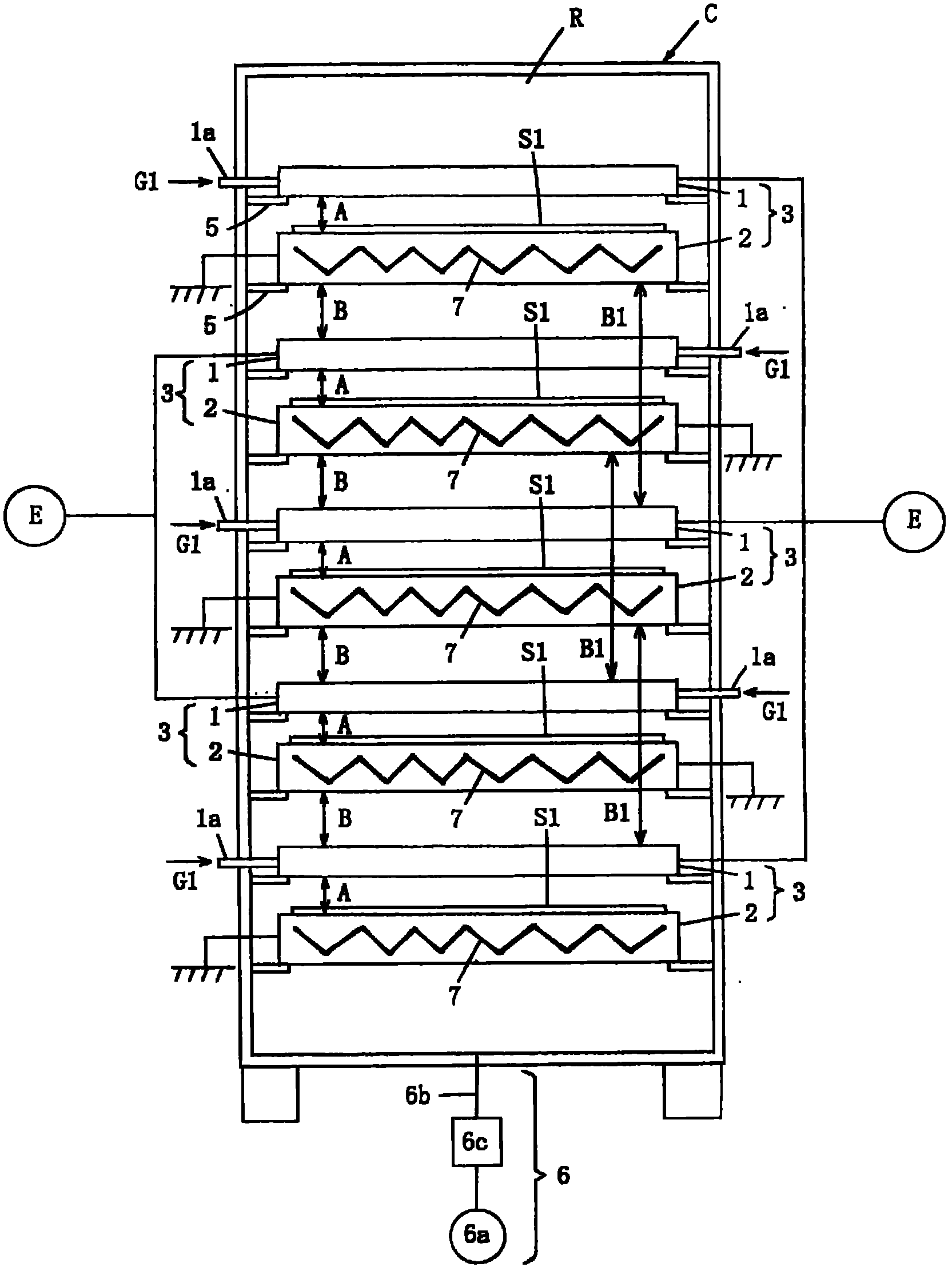
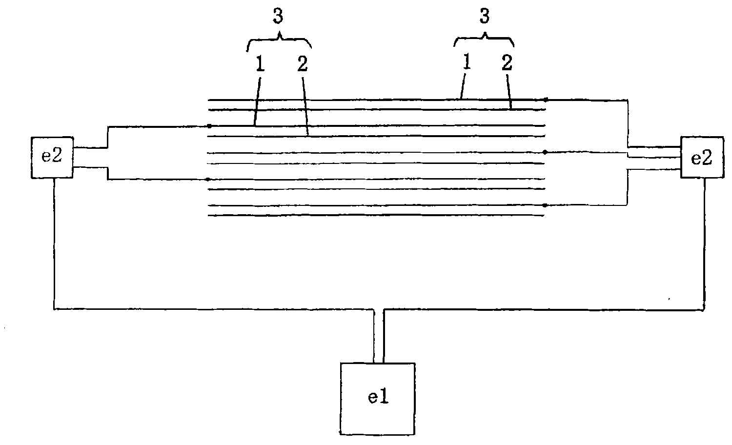
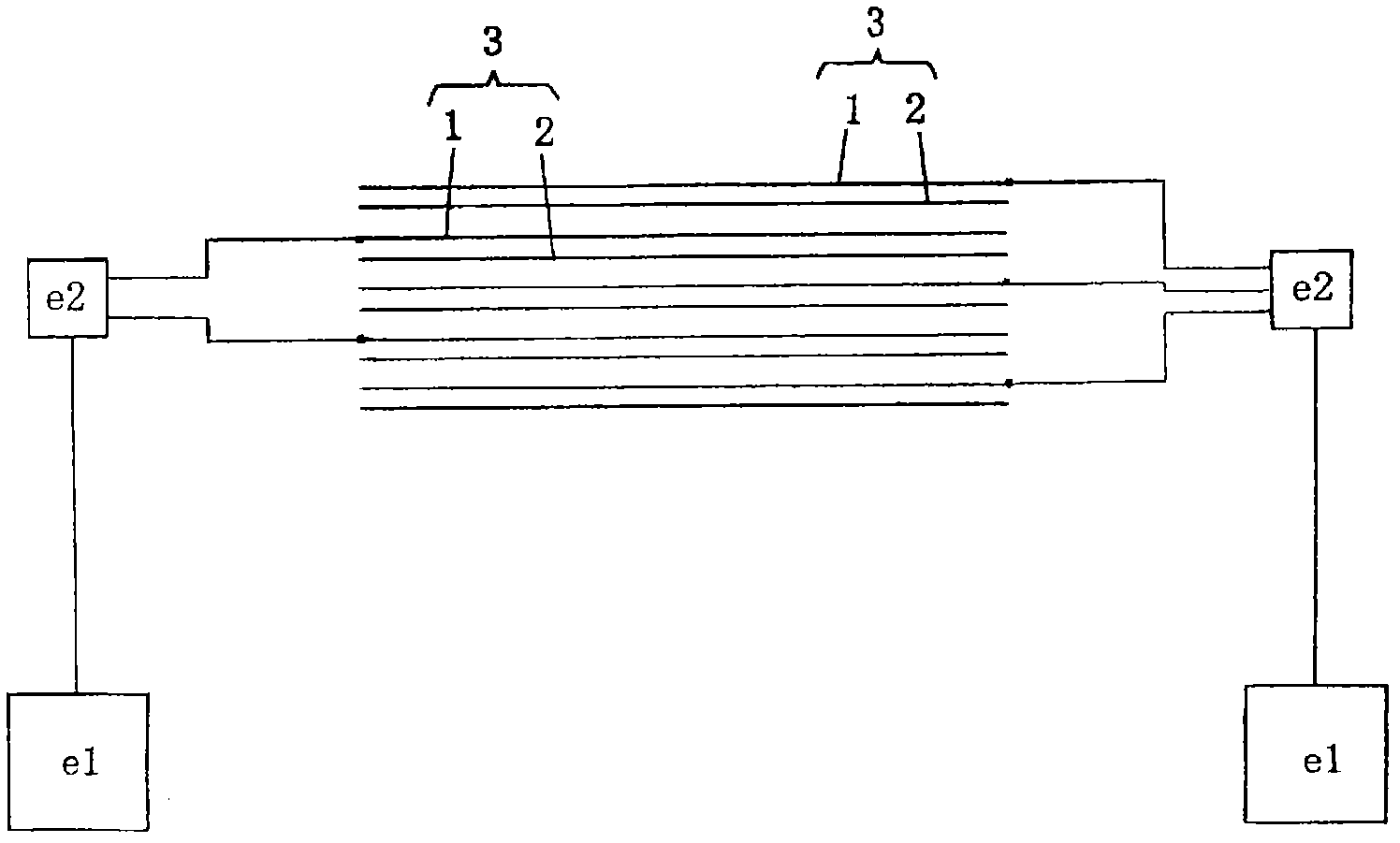
[0077] figure 1 It is a schematic configuration diagram showing Embodiment 1 of the plasma processing apparatus of the present invention. figure 2 It is an explanatory diagram showing the first power supply connection form of Embodiment 1, image 3 It is an explanatory diagram showing the second power supply connection form of the first embodiment.

[0078] The plasma processing apparatus of Embodiment 1 is a vertical side-by-side type plasma processing apparatus for coating a desired film on the surface of the substrate S1 as an object to be processed, and includes: a reaction chamber R, an introduction to the reaction chamber R The gas introduction part 1a for the reaction gas G1, the exhaust part 6 for discharging the reaction gas G1 from the reaction chamber R, and the first electrode 1 and the second electrode 1 which are arranged in a facing state in the reaction chamber R and perform plasma discharge in the reaction gas G1 Three or more sets of discharge parts 3 com...

Embodiment approach 2

[0110] Figure 5 It is a schematic configuration diagram showing Embodiment 2 of the plasma processing apparatus of the present invention. In addition, in Figure 5 in, right with Figure 1 to Figure 4 The same reference numerals are assigned to the same constituent elements as those shown.

[0111] The plasma processing apparatus of Embodiment 2 is also a plasma processing apparatus for coating, but differs from Embodiment 1 (vertical side-by-side type) mainly in that it is a left-right side-by-side type. That is, in the plasma processing apparatus of Embodiment 2, the figure 1 The plasma processing apparatus having the structure of Embodiment 1 described in .

[0112] exist Figure 5 , omitting the illustration shows the figure 1 The chamber C, the support part 5, and the exhaust part 6 are depicted in , but the plasma processing apparatus according to Embodiment 2 also includes these. Among them, in the case of Embodiment 2, the support part supports the negative e...

Embodiment approach 3

[0118] Figure 6 It is a schematic configuration diagram showing Embodiment 3 of the plasma processing apparatus of the present invention. In addition, in Figure 6 in, right with figure 1 Structural elements that are the same as those shown are assigned the same reference numerals.

[0119] The plasma processing apparatus of Embodiment 3 is a vertically arranged plasma processing apparatus for etching. Like Embodiment 1, it has a plurality of sets of discharge parts 13 composed of negative electrodes 11 and positive electrodes 12, and has a chamber not shown in the figure. , support portion, and exhaust portion.

[0120] The main difference between the third embodiment and the first embodiment is that the negative electrode 11 and the positive electrode 12 are arranged upside down in each discharge part 13, the substrate S2 is provided on the negative electrode 11 connected to the power supply part E, and the grounded positive electrode The electrode 2 is arranged above ...


PUM


Abstract

A plasma processing apparatus is provided with a reaction chamber; a gas introducing section for introducing a reaction gas into the reaction chamber; an air release section for releasing the reaction gas from the reaction chamber; three or more pairs of electric discharge sections, each pair of which is composed of a first electrode and a second electrode, arranged to face each other in the reaction chamber and perform plasma discharge in the reaction gas; a supporting section which horizontally or vertically supports the first electrode and the second electrode in parallel; and a power supply section for supplying all the pairs of electric discharge sections with power. The power supply section is provided with high frequency generator, and an amplifier which amplifies high frequency power supplied from the high frequency generator and supplies the first electrode with the amplified power. In the electric discharge section, the first electrode of one electric discharge section and that of other electric discharge section adjacent to the electric discharge section are connected to the same high frequency generator through individual amplifiers or connected to different high frequency generators through the amplifiers, and the second electrodes in the electric discharge sections are grounded, respectively.

Description

technical field [0001] The present invention relates to a plasma processing device, and more specifically, relates to a structure of a plasma processing device formed by arranging a plurality of positive / negative electrode bodies for generating plasma discharge in a chamber. Background technique [0002] As a conventional plasma processing apparatus in which a plurality of sets of positive / negative electrode bodies for generating plasma discharge are arranged vertically in multiple stages in a cavity, for example, the plasma processing apparatus described in Patent Document 1 can be cited. [0003] Among the plurality of upper and lower electrodes of the plasma processing apparatus, the uppermost electrode and each electrode skipped therefrom are negative electrodes electrically connected to a high-frequency power supply, and the remaining electrodes are positive electrodes grounded. [0004] In addition, the plasma processing apparatus is configured such that heaters are pr...

Claims


Application Information

Patent Timeline
Patent Type & Authority Applications(China)
IPC IPC(8): H05H1/46C23C16/509H01L21/205H01L21/3065
CPCH05H1/24C23C16/5096H05H1/2418H01J37/32541H01J37/32568H01J37/32174H01J37/32
Inventor 岸本克史福冈裕介
Owner SHARP KK
Why Eureka
Try Eureka