Planetary gear device

A technology of planetary gears and internal gears, used in gear transmissions, hoisting devices, transmissions, etc., can solve problems such as difficulty in securing a large space

Active Publication Date: 2011-05-04
SUMITOMO HEAVY IND LTD
View PDF8 Cites 8 Cited by
  • Summary
  • Abstract
  • Description
  • Claims
  • Application Information

AI Technical Summary

Problems solved by technology

[0010] However, since the existence of the inner pin 22 restricts the size in the radial direction, it is extremely difficult to ensure a large

Method used


Image

  • Planetary gear device
  • Planetary gear device
  • Planetary gear device

Examples


Embodiment Construction

[0030] Hereinafter, an example of embodiment of the present invention will be described in detail with reference to the drawings.

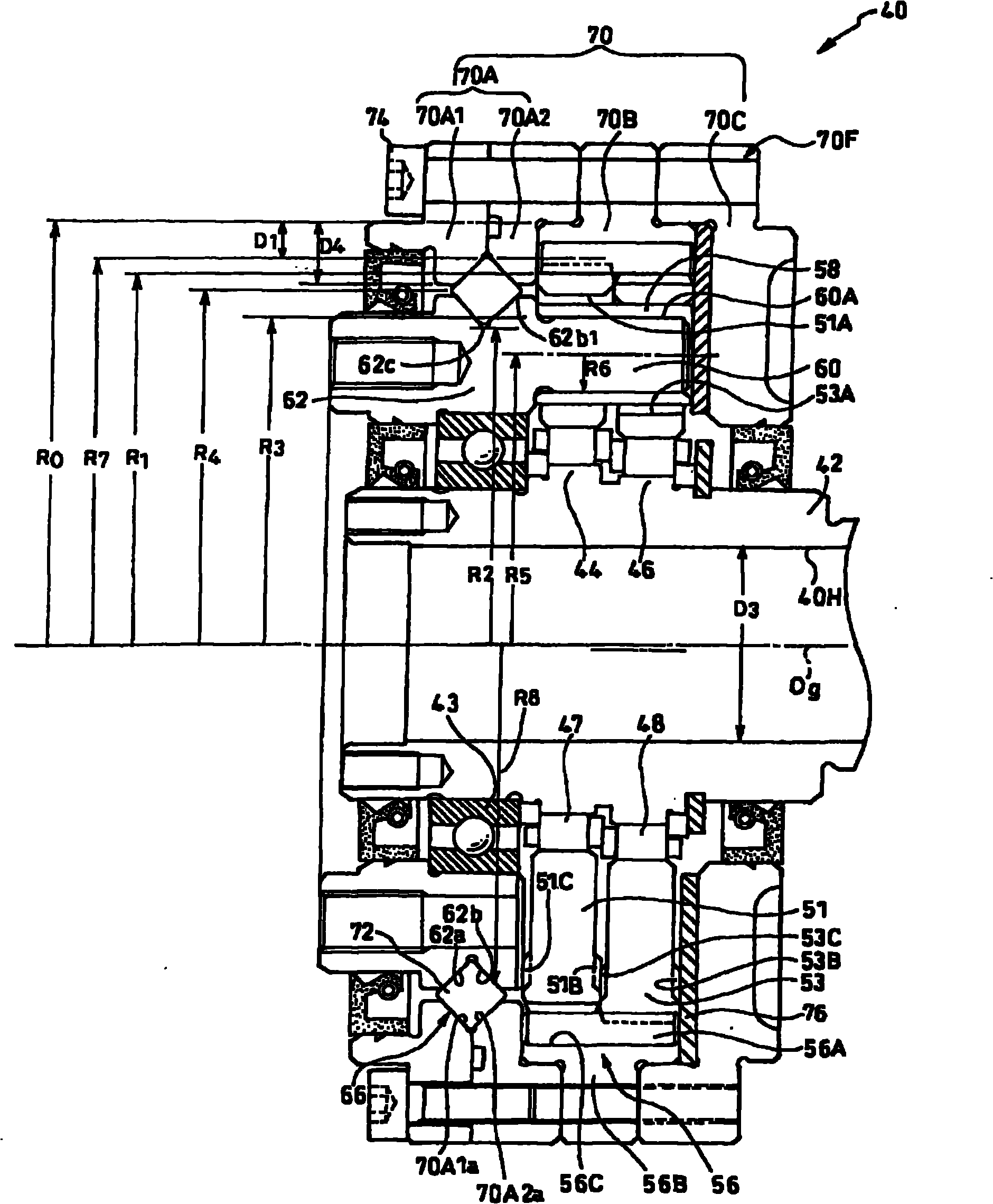
[0031] figure 1 It is a cross-sectional view showing a planetary gear speed reducer according to an example of an embodiment of the present invention.

[0032] The planetary gear reduction device 40 has a hollow portion 40H that axially penetrates the device 40 (penetrates along the axis Og of the device 40 ) in the space at the central portion in the radial direction. This planetary gear reduction unit 40 includes an input shaft (high-speed shaft) 42, two eccentric bodies 44, 46, two rollers 47, 48, two external gears (planetary gears) 51, 53, and external gears 51, 53. meshing internal gear 56 . This device has a structure in which the relative rotation component of the external gears 51 and 53 and the internal gear 56 is taken out as an output through the internal pin (pin member) 60 and the carrier flange 62 by swinging the external gears 5...


PUM


Abstract

The present invention provides a planetary gear device which ensures a large space at a central part in a radius direction of the device without enlarging the dimension in a radius direction of the whole body of the planetary gear device. An inner pin (pin component) which projects from a gear frame flange (62) and penetrates through outer gears (51,53) is formed integrally with the gear frame flange (62). The most outer peripheral outer (60A) of the inner pin (60) is provided more adjacently to the outside in a radius direction compared with the inner ring side rolling surfaces (62a,62b) of a cross roller bearing (main bearing) (66) which is used for supporting the gear frame flange (62) on a housing (70) or a least radius part (62c) of an elongated surface.

Description

technical field [0001] This application claims priority based on Japanese Patent Application No. 2009-241725 filed on October 20, 2009. All the content of the application is used in this specification by reference. [0002] The present invention relates to a planetary gear device. Background technique [0003] For example, disclosed in Patent Document 1 as Figure 7 A planetary gear reduction unit with a hollow portion is shown. [0004] This planetary gear reducer 10 includes three pieces of external gears 11 to 13 and an internal gear 14 internally meshed with the external gears 11 to 13, and is a device that takes out the relative rotation component between the external gears 11 to 13 and the internal gear 14 as an output. structure. A hollow portion 10H penetrating the planetary gear reduction device 10 in the axial direction is formed at a central portion in the radial direction of the planetary gear reduction device 10 . This hollow portion 10H is passed through by...

Claims


Application Information

Patent Timeline
IPC IPC(8): F16H1/28F16H57/02F16H57/08F16H55/17F16H55/10F16C33/32F16H1/32
CPCF16H1/32F16H2001/323
Inventor 芳贺卓志津庆刚
Owner SUMITOMO HEAVY IND LTD
Why Eureka
Try Eureka