
Circulating fluidized bed refuse incineration boiler and refuse incineration method thereof

A circulating fluidized bed and waste incineration technology, which is applied in the combustion method, incinerator, combustion type, etc., can solve the problems of loss, inability to judge, and the structure and composition of the sanitation belt are not specified in detail, so as to reduce operating costs and improve Flue gas temperature, the effect of increasing adaptability

Active Publication Date: 2011-05-04
烟台鑫丰源电站设备有限公司
View PDF3 Cites 24 Cited by
  • Summary
  • Abstract
  • Description
  • Claims
  • Application Information

AI Technical Summary

Problems solved by technology

Due to the current high coal price in my country, the operating cost of waste-to-energy plants has increased significantly, and some are even on the verge of losing money
The application number is "00108520.4", and the waste incineration boiler disclosed in the Chinese invention patent application document named "Municipal Domestic Garbage Internal Circulation Different Density Fluidized Bed Incineration Boiler" does not involve the heat insulation problem of its combustion chamber; the application number is "200410009082.2 ", the CFB boiler disclosed in the Chinese invention patent application titled "A Circulating Fluidized Bed Boiler for Burning Household Garbage", although a membrane-type water-cooled wall is installed in the combustion chamber to reduce heat absorption, ensuring that the combustion chamber Combustion temperature guard combustion zone, but the structure and composition of the guard combustion zone are not detailed. From the public documents, it is impossible to judge how the guard combustion zone can reduce the heat absorption of the membrane water wall and ensure the combustion temperature in the combustion chamber.

Method used


Image

  • Circulating fluidized bed refuse incineration boiler and refuse incineration method thereof
  • Circulating fluidized bed refuse incineration boiler and refuse incineration method thereof
  • Circulating fluidized bed refuse incineration boiler and refuse incineration method thereof

Examples


Embodiment Construction

[0080] Below in conjunction with accompanying drawing, structure principle and working principle of the present invention are described in detail:

[0081] In order to solve the problems of low calorific value and large fluctuation of garbage, poor combustion stability, low combustion temperature in the furnace, which affects the decomposition of dioxins, and strong corrosive acid gas in the flue gas, the invention adopts a different type of conventional garbage in the overall structure of the boiler. Structural design of coal-fired mixed fuel circulating fluidized bed boiler.

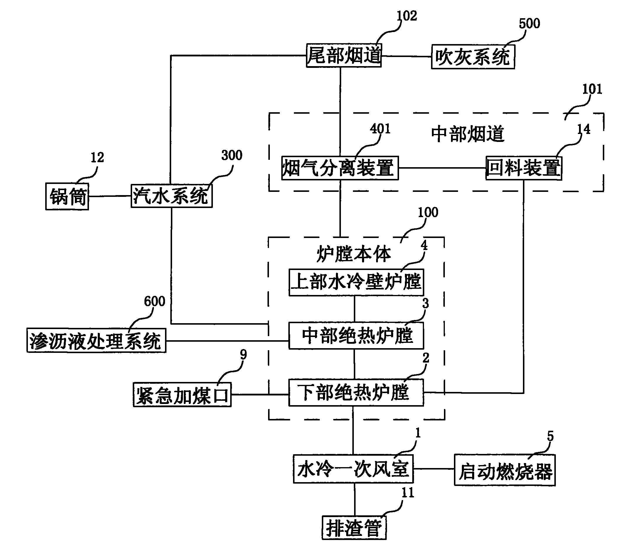
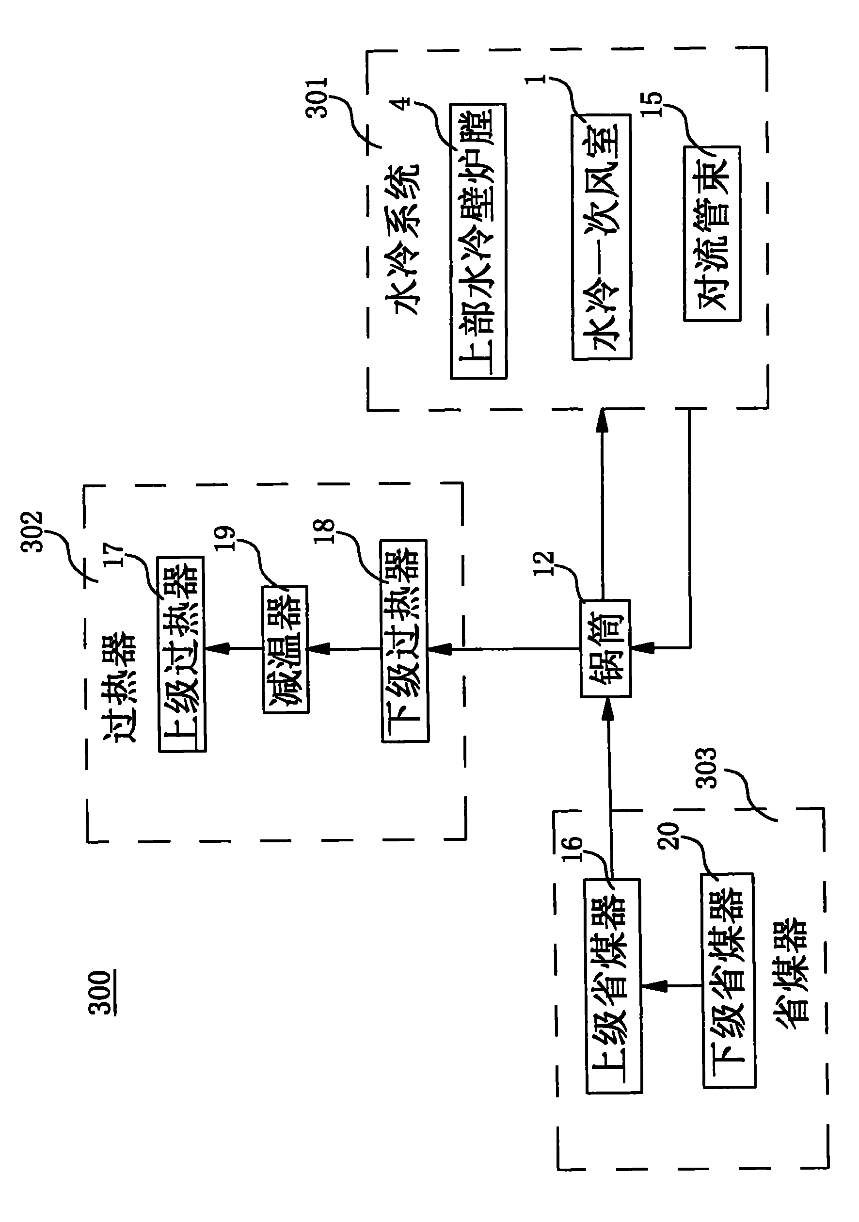
[0082] see figure 1 and Image 6 , figure 1 It is a structural block diagram of the circulating fluidized bed waste incineration boiler of the present invention, Image 6 It is a schematic structural diagram of the circulating fluidized bed waste incineration boiler of the present invention. The circulating fluidized bed waste incineration boiler of the present invention includes a steel frame 25 a...


PUM


Abstract

The invention relates to a circulating fluidized bed refuse incineration boiler and a refuse incineration method thereof. The boiler comprises a steel framework and a hearth body, a middle flue, a tail flue and a boiler barrel which are arranged on the steel framework. A smoke separation device and a return device are arranged in the middle flue; the smoke separation device and the return device are respectively connected with the hearth body; the tail flue and the smoke separation device are connected; vapor-water systems are arranged in the hearth body and the tail flue; the vapor-water systems are connected with the boiler barrel; the hearth body comprises an upper water cooled wall hearth, a lower insulation hearth and a middle insulation hearth, wherein the middle insulation hearth and the lower insulation hearth are hearth structures without heating surfaces and are used for preventing heat loss generated after refuse is burnt so as to make the heat used for preheating and igniting new put refuse. The refuse incineration boiler and the incineration method thereof reduce the operating cost of a refuse power station and enhance the adaptability to refuse quality changes.

Description

technical field [0001] The invention relates to a garbage power generation equipment, in particular to a circulating fluidized bed garbage incineration boiler and a garbage incineration method. Background technique [0002] At present, with the acceleration of urbanization and the improvement of people's living standards, urban residents' domestic garbage disposal has become an important part of environmental protection. In 2007, the total amount of garbage in my country's 655 cities reached 125 million tons. Many cities are facing "garbage siege", and the harmless disposal of garbage has become one of the most important environmental protection issues. [0003] Among the three methods of harmless waste treatment, waste incineration power generation is the treatment method that is closest to the three principles of harmlessness, reduction and recycling of waste. Therefore, it has begun to develop in my country. Among them, the equipment investment of circulating fluidized b...

Claims


Application Information

Patent Timeline
IPC IPC(8): F23G5/30F23G5/08F23G5/44
Inventor 董凯张天飚
Owner 烟台鑫丰源电站设备有限公司
Learn More