Improved scan chain unit and non-concurrent testing method based on same

A scan chain and scan data technology, applied in the non-concurrent online testing field, can solve the problems of strict timing requirements, difficult control, and inability to move into multiple sets of test vectors at one time, so as to improve test efficiency and simplify timing control.

Inactive Publication Date: 2011-05-04
HARBIN INST OF TECH
View PDF5 Cites 26 Cited by
  • Summary
  • Abstract
  • Description
  • Claims
  • Application Information

AI Technical Summary

Problems solved by technology

[0006] The purpose of the present invention is to solve the problems that the existing non-concurrent online test method based on scan chains has strict requirements on timing, d

Method used


Image

  • Improved scan chain unit and non-concurrent testing method based on same
  • Improved scan chain unit and non-concurrent testing method based on same
  • Improved scan chain unit and non-concurrent testing method based on same

Examples


specific Embodiment approach 1

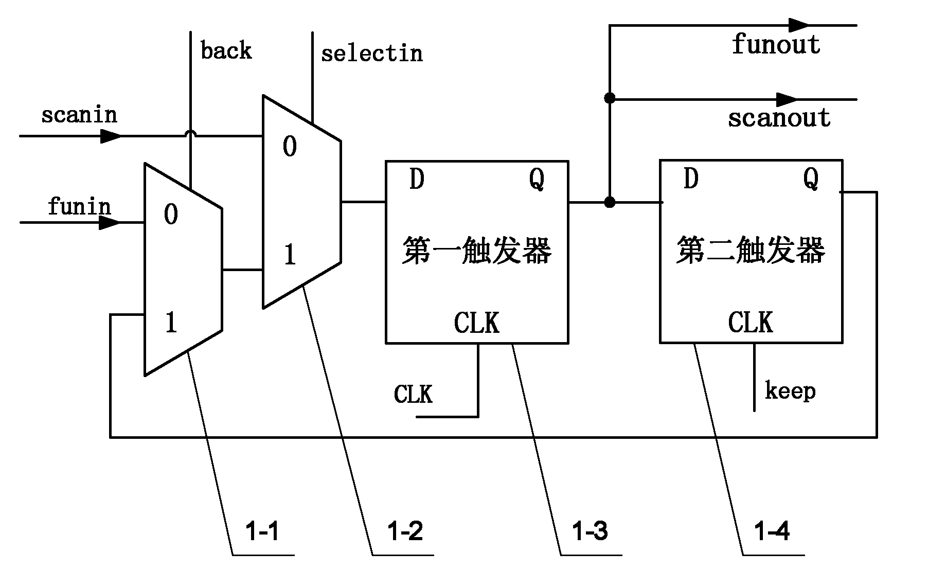
[0049] Specific implementation mode one: the following combination Figure 1 to Figure 8 Describe this embodiment, the improved scan chain unit 1 in this embodiment includes a first selector 1-1, a second selector 1-2, a first flip-flop 1-3 and a second flip-flop 1-4, the first The 0 input terminal of the selector 1-1 is used as the functional data input terminal of the improved scan chain unit 1, the 1 input terminal of the first selector 1-1 is connected with the output terminal of the second flip-flop 1-4, and the first selection The output terminal of the device 1-1 is connected with the 1 input terminal of the second selector 1-2, and the 0 input terminal of the second selector 1-2 is used as the test unit scan data input terminal of the improved scan chain unit 1, and the second The output end of the selector 1-2 is connected with the D signal input end of the first flip-flop 1-3, the output end of the first flip-flop 1-3 is connected with the D signal input end of the s...

specific Embodiment approach 2

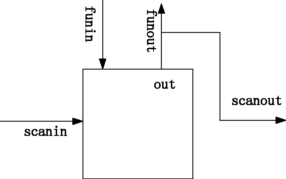
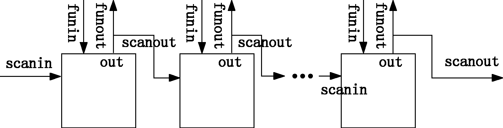
[0065] Specific implementation mode two: the following combination Figure 1 to Figure 9 , Figure 12 This embodiment is described. This embodiment is based on the online test method of the improved scan chain unit described in Embodiment 1. The improved scan chain unit 1 is connected as a D flip-flop into the sequential logic circuit of the system on chip. The improved scan chain unit 1 The functional data input end of the D flip-flop is used as the D input end of the D flip-flop, and the functional data output end of the improved scan chain unit 1 is used as the Q output end of the D flip-flop. All the improved scan chain units 1 are connected in series from the beginning to the end to form a scan chain. The scan data input end of the improved scan chain unit 1 at the head end of the scan chain is connected to the signal output end of the test stimulus module 2, and its scan data output end is connected to the scan data input end of the next improved scan chain unit 1 in the...

specific Embodiment approach 3

[0086] Specific implementation mode three: the following combination Figure 10 and Figure 11 Describe this embodiment, this embodiment is set for the situation that there are a lot of D flip-flops in the system on chip, and the difference with the second embodiment is that all the improved scan chain units 1 are divided into multiple groups, and the The improved scan chain unit 1 is serially connected into a scan chain, and multiple scan chains formed by the improved scan chain unit 1 are all arranged in parallel, and the test unit scan data input terminal of each scan chain is connected to the signal output end of the test excitation module 2, each The scan data output terminal of the scan chain is connected to the response signal input terminal of the test response module 3 , and the test vectors sent by the test excitation module 2 to multiple scan chains are kept in sync. Other structures and steps are the same as those in Embodiment 2.

[0087] The number of improved ...


PUM


Abstract

The invention relates to an improved scan chain unit and a non-concurrent testing method based on the same, which belongs to the filed of on-chip system testing and aims at solving the problems that the existing scan chain-based non-concurrent on-line testing method has strict requirements for time sequences, is difficult to control and can not realize the one-step import of multiple groups of test vectors. The improved scan chain unit is used for replacing a D trigger in an on-chip system, and the unit contains two triggers and two selectors, wherein a first trigger is a basic unit which composes the original circuit scan chain and is used for realizing the function same with that of the original D trigger, and a second trigger is introduced for saving data in the testing process; and the two data selectors control the flow direction of data by means of enable ends, a first selector is used for controlling whether data in the second trigger can be transmitted to the first trigger, and a second selector is used for controlling the working state or the scanning state of the first trigger. Thus, multiple groups of test vectors can be input to the unit for continuous testing, and therunning state of the circuit is not changed before and after the test.

Description

technical field [0001] The invention relates to an improved scan chain unit and a non-concurrent online testing method based on the unit, which belongs to the field of on-chip system testing. Background technique [0002] System-on-a-Chip (SOC), also known as system-on-chip, is a system-level integrated circuit, which can integrate complex systems (including digital circuits, analog circuits, signal acquisition and Conversion circuit, memory, MPU, DSP, MPEG, etc.) are integrated on one chip. As the fault discovery time in SOC is delayed, the economic loss caused by the fault will increase exponentially. Compared with offline testing, online testing can find faults and deal with them during system operation, so it can effectively reduce the cost caused by faults. Economic loss caused by failure. And with the development of industry, military and aerospace technology, in some SOCs with special purposes, it is required that the test must be carried out simultaneously with the...

Claims


Application Information

Patent Timeline
IPC IPC(8): G01R31/317G01R31/3181
Inventor 俞洋杨智明付宁王帅乔立岩彭喜元
Owner HARBIN INST OF TECH
Why Eureka
Try Eureka