Improved scan chain unit and non-concurrent testing method based on same
A test method and scan chain technology, applied in the field of non-concurrent online testing, can solve the problems of strict timing requirements, difficult control, and inability to move multiple sets of test vectors at a time, so as to improve test efficiency and simplify timing control.
- Summary
- Abstract
- Description
- Claims
- Application Information
AI Technical Summary
Problems solved by technology
Method used
Image
Examples
specific Embodiment approach 1
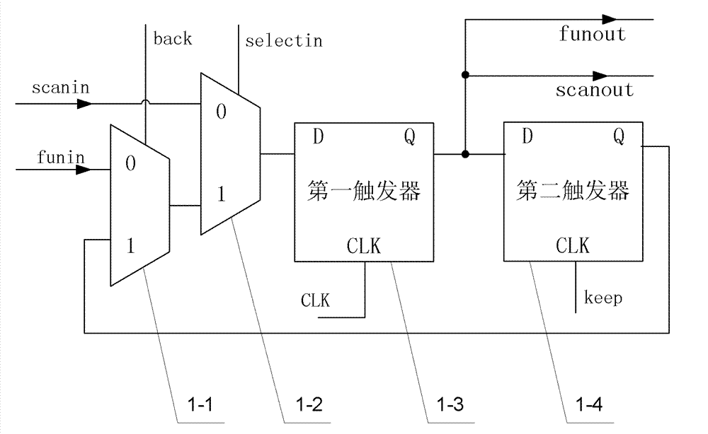
[0049] Specific implementation mode one: the following combination Figure 1 to Figure 8 Describe this embodiment, the improved scan chain unit 1 in this embodiment includes a first selector 1-1, a second selector 1-2, a first flip-flop 1-3 and a second flip-flop 1-4, the first The 0 input terminal of the selector 1-1 is used as the functional data input terminal of the improved scan chain unit 1, the 1 input terminal of the first selector 1-1 is connected with the output terminal of the second flip-flop 1-4, and the first selection The output terminal of the device 1-1 is connected with the 1 input terminal of the second selector 1-2, and the 0 input terminal of the second selector 1-2 is used as the test unit scan data input terminal of the improved scan chain unit 1, and the second The output end of the selector 1-2 is connected with the D signal input end of the first flip-flop 1-3, the output end of the first flip-flop 1-3 is connected with the D signal input end of the s...
specific Embodiment approach 2
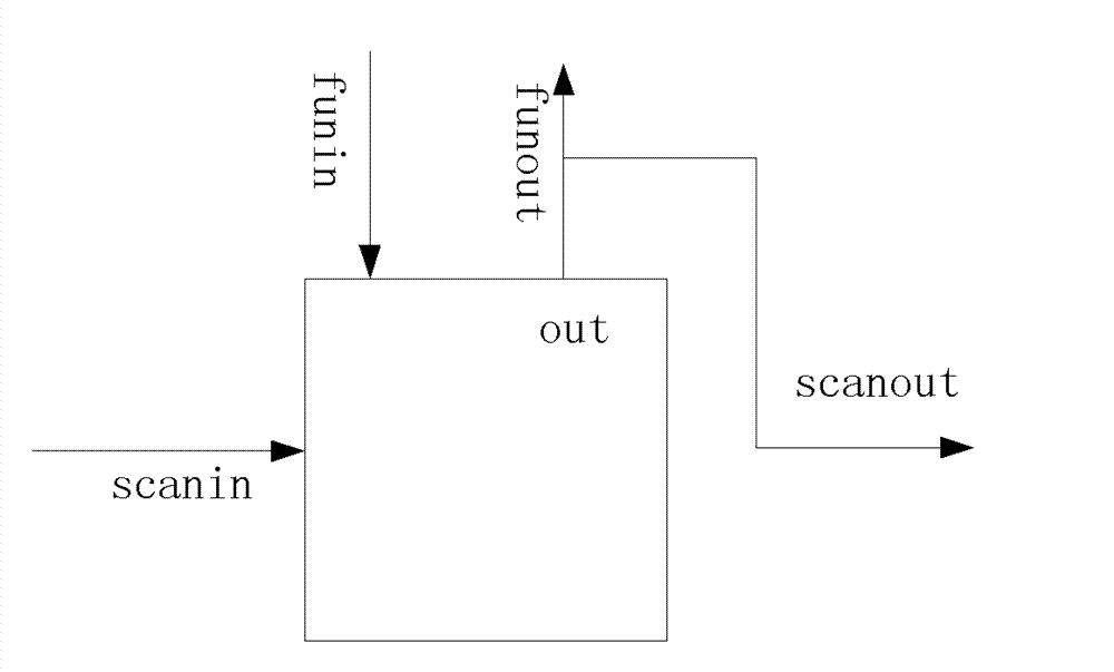
[0064] Specific implementation mode two: the following combination Figure 1 to Figure 9 , Figure 12 This embodiment is described. This embodiment is based on the online test method of the improved scan chain unit described in Embodiment 1. The improved scan chain unit 1 is connected as a D flip-flop into the sequential logic circuit of the system on chip. The improved scan chain unit 1 The functional data input end of the D flip-flop is used as the D input end of the D flip-flop, and the functional data output end of the improved scan chain unit 1 is used as the Q output end of the D flip-flop. All the improved scan chain units 1 are connected in series from the beginning to the end to form a scan chain. The scan data input end of the improved scan chain unit 1 at the head end of the scan chain is connected to the signal output end of the test stimulus module 2, and its scan data output end is connected to the scan data input end of the next improved scan chain unit 1 in the...
specific Embodiment approach 3
[0085] Specific implementation mode three: the following combination Figure 10 and Figure 11 Describe this embodiment, this embodiment is set for the situation that there are a lot of D flip-flops in the system on chip, and the difference with the second embodiment is that all the improved scan chain units 1 are divided into multiple groups, and the The improved scan chain unit 1 is serially connected into a scan chain, and multiple scan chains formed by the improved scan chain unit 1 are all arranged in parallel, and the test unit scan data input terminal of each scan chain is connected to the signal output end of the test excitation module 2, each The scan data output terminal of the scan chain is connected to the response signal input terminal of the test response module 3 , and the test vectors sent by the test excitation module 2 to multiple scan chains are kept in sync. Other structures and steps are the same as those in Embodiment 2.
[0086] The number of improved ...
PUM
 Abstract
Description
Claims
Application Information
 - R&D
- Intellectual Property
- Life Sciences
- Materials
- Tech Scout
- Unparalleled Data Quality
- Higher Quality Content
- 60% Fewer Hallucinations
Browse by: Latest US Patents, China's latest patents, Technical Efficacy Thesaurus, Application Domain, Technology Topic, Popular Technical Reports.
© 2025 PatSnap. All rights reserved.Legal|Privacy policy|Modern Slavery Act Transparency Statement|Sitemap|About US| Contact US: help@patsnap.com


