Equipment for preparing catalytic cracking catalyst

A catalytic cracking and catalyst technology, used in catalytic cracking, catalyst activation/preparation, physical/chemical process catalysts, etc., can solve the problems of low production efficiency, high labor intensity, endangering the health of operators, etc., and achieve stable product performance. The effect of low labor intensity and high production efficiency

Active Publication Date: 2011-05-11
CHINA PETROLEUM & CHEM CORP +1
View PDF3 Cites 21 Cited by
  • Summary
  • Abstract
  • Description
  • Claims
  • Application Information

AI Technical Summary

Problems solved by technology

And, in the method of above-mentioned prior art, in order to guarantee the high silicon content of the obtained molecular sieve, generally all make SiCl 4 far excess, excess SiCl 4 Undoubtedly increased production costs and environmental protection costs
On the other hand, the above-mentioned methods all require very complicated manual operations, such as: manual loading, manual unloading and long-term purging of pipelines

Method used


Image

  • Equipment for preparing catalytic cracking catalyst
  • Equipment for preparing catalytic cracking catalyst
  • Equipment for preparing catalytic cracking catalyst

Examples


Embodiment approach

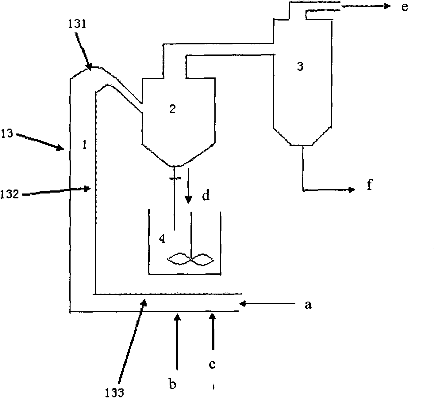
[0021] According to a preferred embodiment of the present invention, the pipe body 13 further includes a second inclined section 133, one end of the second inclined section 133 is connected to the other end of the vertical section 132, and the first The feed port is located at the other end of the second inclined section 133 . Such setting can prevent the molecular sieve solid material from flowing too fast under the action of gravity, and increase the contact reaction time between the reaction materials.

[0022] Further preferably, the position of the first feed inlet is higher than the position where the second inclined section 133 is connected to the vertical section 132, so that the molecular sieve solid material can directly enter the second inclined section 133 by its own gravity. In section 133, it can then be transported further under the entrainment of the carrier gas.

[0023] According to the device provided by the present invention, the included angle between the...

Embodiment 1

[0038] Made of industrial grade stainless steel with a thickness of 3mm NiCr18Ti figure 2 In the shown molecular sieve vapor phase silicon replenishment equipment, the tube body 13 of the tubular reactor 1 is composed of a first inclined section 131, a vertical section 132 and a second inclined section 133, the length of the first inclined section 131 is 20 meters, and the diameter is 0.8 meters, the length of the vertical section 132 is 40 meters, and the diameter is 0.8 meters. The length of the second inclined section 133 is 15 meters, and the diameter is 0.8 meters. The vertical section 132 is perpendicular to the horizontal plane, and the axis of the first inclined section 131 and The angle between the horizontal planes is 75°, the angle between the axis of the second inclined section 133 and the horizontal plane is 65°, and the port of the second inclined section 132 is the first feed inlet, which is 3° away from the first feed inlet. The positions of 8 meters and 8 met...

Embodiment 2

[0041] Made of industrial grade stainless steel with a thickness of 3mm NiCr18Ti figure 2 In the shown molecular sieve vapor phase silicon replenishment equipment, the tube body 13 of the tubular reactor 1 is composed of a first inclined section 131, a vertical section 132 and a second inclined section 133, the length of the first inclined section 131 is 25 meters, and the diameter is 0.4 meters, the length of the vertical section 132 is 45 meters, and the diameter is 0.4 meters. The length of the second inclined section 133 is 25 meters, and the diameter is 0.4 meters. The vertical section 132 is perpendicular to the horizontal plane, and the axis of the first inclined section 131 and The angle between the horizontal planes is 55°, the angle between the axis of the second inclined section 133 and the horizontal plane is 55°, and the port of the second inclined section 132 is the first feed inlet, which is 6° away from the first feed inlet. The positions of 10 meters and 10 met...


PUM

PropertyMeasurementUnit
Lengthaaaaaaaaaa

Abstract

The invention relates to equipment for preparing a catalytic cracking catalyst, which comprises a tubular reactor, a gas-solid separator, an absorption column, a beating machine and a nodulizer, wherein the tubular reactor comprises a first feeding hole, a discharging hole and a tube body, and the first feeding hole and the discharging hole are respectively positioned at two end parts of the tubebody; the tubular reactor is communicated with the gas-solid separator through the discharging opening, the upper part and the lower part of the gas-solid separator are respectively communicated withthe absorption column and the beating machine, the position where the gas-solid separator is connected with the discharging hole is lower than that where the gas-solid separator is connected with theabsorption column, and the nodulizer is used for receiving materials from the beating machine. The equipment for preparing the catalytic cracking catalyst, provided by the invention, can realize continuous operation of the contact reaction of the molecular sieve and SiCl4, and can control the contact time of the molecular sieve and the SiCl4 through controlling the length of the tubular reactor and the flow speed of the carrier gas, thereby being capable of enabling the contact reaction of the molecular sieve with the SiCl4 to be fully carried out in the tubular reactor.

Description

technical field [0001] The invention relates to a device for preparing catalytic cracking catalyst. Background technique [0002] Molecular sieve is a widely used material in catalytic cracking catalyst, and it is also a very important component. The performance of molecular sieve directly affects the reaction performance of catalytic cracking catalyst. According to different needs, molecular sieves can be modified differently to meet the requirements of use. For example, molecular sieves with a high silicon-to-aluminum ratio are generally considered to be required for catalytic cracking catalysts. [0003] In the preparation of molecular sieves with a high silicon-aluminum ratio, there are mainly the following methods: ammonium fluorosilicate method for aluminum and silicon supplementation, hydrothermal method for aluminum and silicon supplementation, and gas phase chemical method for aluminum and silicon supplementation. [0004] The method of ammonium fluorosilicate to ...

Claims


Application Information

Patent Timeline
IPC IPC(8): B01J37/00B01J29/16C10G11/05
Inventor 许明德田辉平朱玉霞周灵萍张蔚琳任飞
Owner CHINA PETROLEUM & CHEM CORP
Why Eureka
Try Eureka