Force servo-controlled power-driven manipulator

An electric manipulator and servo control technology, applied in the direction of program control manipulators, manipulators, manufacturing tools, etc., can solve problems such as limited life, affecting operating performance, inconvenient operation, etc., to achieve accurate positioning and fast movement, reduce labor intensity, solve problems Inconvenient effect

Inactive Publication Date: 2011-05-11
上海永乾机电有限公司
View PDF1 Cites 10 Cited by
  • Summary
  • Abstract
  • Description
  • Claims
  • Application Information

AI Technical Summary

Problems solved by technology

Most of the existing manipulator manual control uses buttons to control the movement of lifting or walking direction. Button control usually only has single speed or double speed. This structure cannot meet the requirements for precise positioning and fast movement in industrial control, and the operation is very difficult. Inconvenient; in addition, there is also a method of using a potentiometer to control the movement speed of the manipulator, but there are disadvantages of large mechanical transmission errors, limited life, and inability to respond quickly in real time
Therefore, none of the manipulators in the existing control mode can respond to the real-time movement requirements of the manipulator to the machine in real time. laborious and time consuming

Method used


Image

  • Force servo-controlled power-driven manipulator
  • Force servo-controlled power-driven manipulator
  • Force servo-controlled power-driven manipulator

Examples


Embodiment Construction

[0013] The structural features of the force servo controlled electric manipulator of the present invention will be further described below in conjunction with the accompanying drawings and embodiments.

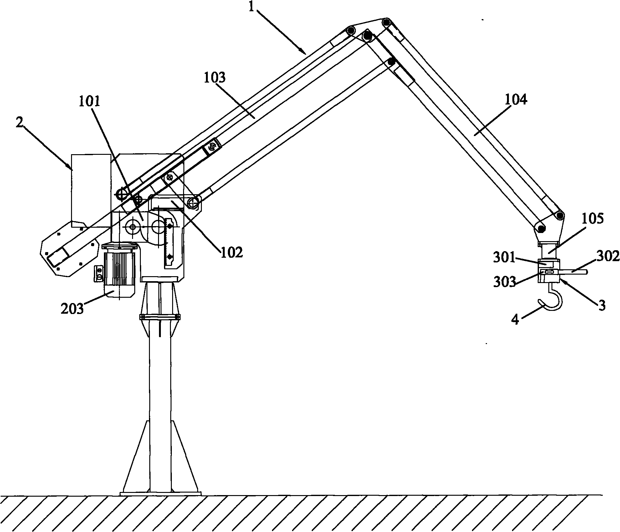
[0014] figure 1 It is a structural schematic diagram of an embodiment of an electric manipulator controlled by force servo in the present invention. Such as figure 1 As shown, the electric manipulator controlled by the force servo of the present invention includes a manipulator body 1 with a lifting hand 4, a control hand 3 and a force feedback control system 2 connected to the control hand 3 to control the manipulator body 1;

[0015] Such as figure 1 As shown, in this embodiment, the manipulator body 1 includes a transmission device 101, a body rotary joint 102 connected to the transmission device 101, a main arm 103 connected to the body rotary joint 102, and a forearm 104 connected to the main arm 103 , is connected to the hand swivel joint 105 on the top of the forearm...


PUM


Abstract

The invention discloses a force servo-controlled power-driven manipulator comprising a manipulator body with a hoisting hand, a control hand and a force feedback control system connected with the control hand; wherein the control hand comprises at least one pulling pressure sensor; the force feedback control system comprises at least one force servo controller, at least one driver and at least one electric motor. The pulling pressure sensor in the control hand receives a signal of a control force and transmits the signal to the force servo controller in the force feedback control system, the force servo controller starts the driver according to the magnitude and the direction of the control force, the driver drives the electric motor to drive the manipulator body to move, and then a hoisted piece hoisted on the hoisting hand of the manipulator body moves on the basis of the speed and the direction controlled by the force servo controller. The pulling pressure sensor can reflect the control requirement of an operator on the power-driven manipulator in real time so that the power-driven manipulator acts like the hand of the operator per se, and the force servo-controlled power-driven manipulator has the characteristics of accuracy in location, sensitivity in response and smoothness and steadiness in motion and is free of impacting shakes.

Description

technical field [0001] The invention relates to an electric manipulator, in particular to an electric manipulator controlled by force servo. Background technique [0002] At present, semi-automatic or manual manipulators are widely used in industrial production. The main control methods of existing manipulators are: according to the working path, the program for controlling the movement part of the manipulator is pre-programmed, and when used, it is executed according to the prepared program to automatically realize the corresponding exercise requirements. Other parts or all adopt manual control. Most of the existing manipulator manual control uses buttons to control the movement of lifting or walking direction. Button control usually only has single speed or double speed. This structure cannot meet the requirements for precise positioning and fast movement in industrial control, and the operation is very difficult. Inconvenient; in addition, there is also a method of usin...

Claims


Application Information

Patent Timeline
Patent Type & Authority Applications(China)
IPC IPC(8): B25J9/08B25J3/04
Inventor 陈强
Owner 上海永乾机电有限公司
Why Eureka
Try Eureka