
Fluctuant waveguide slow wave structure

A slow-wave structure, undulating technology, applied in the field of vacuum electronics, can solve the problems of difficult design of input and output structure of rectangular grid waveguide, high development cost of terahertz power source, and difficult processing of electronic injection channels, and achieves low processing difficulty and reflection. Small, low frequency loss effect

Inactive Publication Date: 2011-05-11
UNIV OF ELECTRONICS SCI & TECH OF CHINA
View PDF4 Cites 8 Cited by
  • Summary
  • Abstract
  • Description
  • Claims
  • Application Information

AI Technical Summary

Problems solved by technology

Due to the shorter working wavelength, the smaller the size of the slow-wave structure, that is, the size co-transition effect, makes these structures have large high-frequency loss and strong reflection when working in the terahertz band.
In addition, the processing of the electron beam channel of the meandering waveguide is very difficult; the input and output structure of the rectangular grid waveguide is difficult to design
Various difficulties make the development cost of the existing terahertz power source high, the cycle is long, and there is still a long way to go before practical application

Method used


Image

  • Fluctuant waveguide slow wave structure
  • Fluctuant waveguide slow wave structure
  • Fluctuant waveguide slow wave structure

Examples


Embodiment Construction

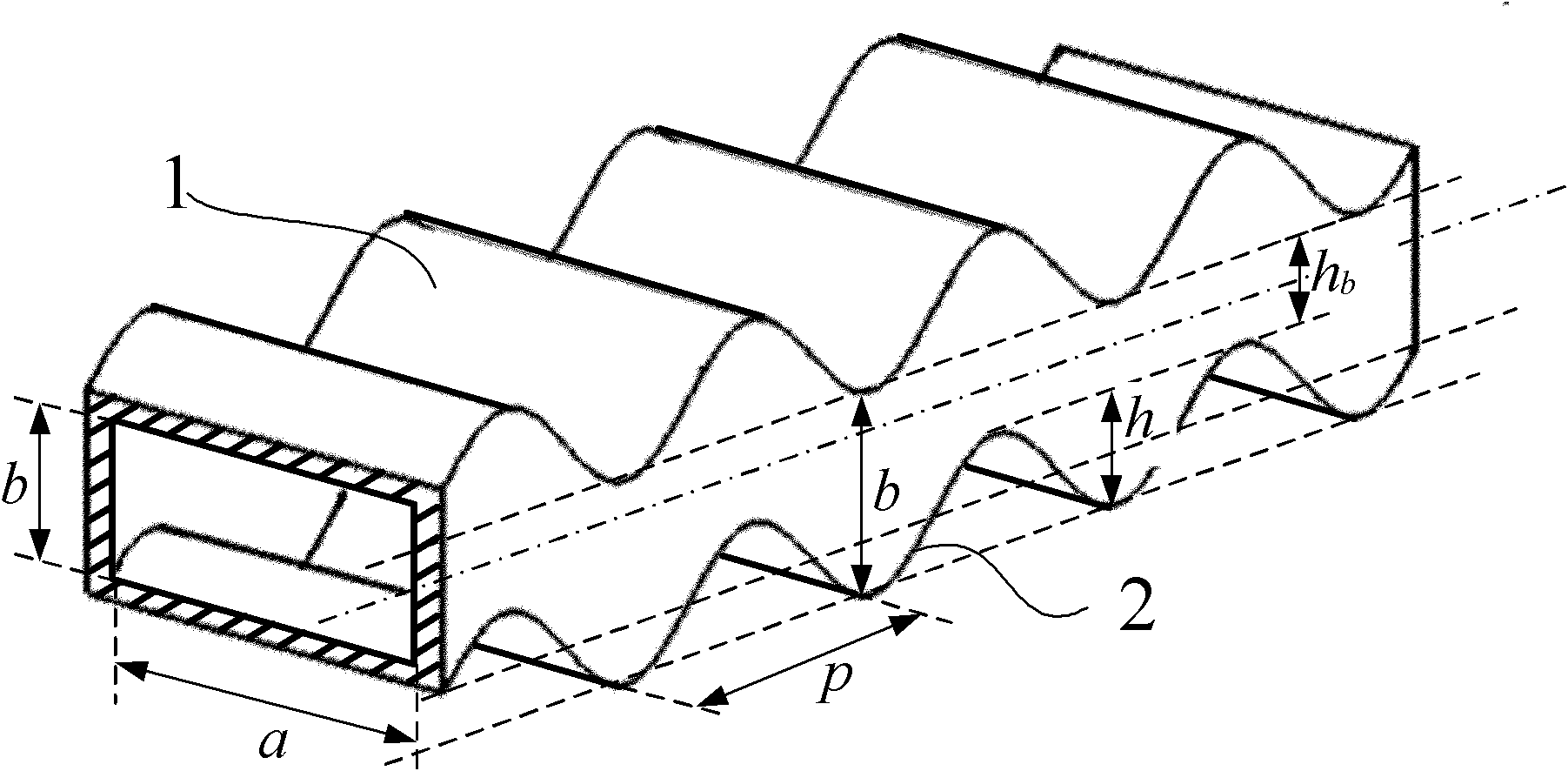
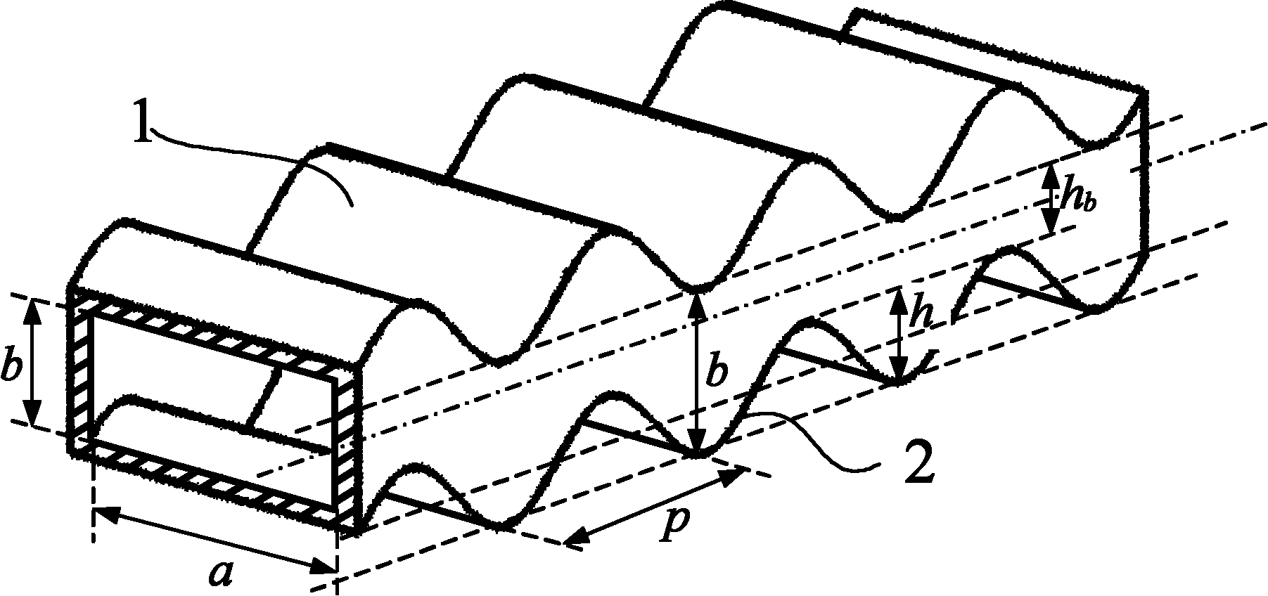
[0019] An undulating waveguide slow-wave structure, such as figure 1 As shown, it is formed by deforming a conventional rectangular waveguide whose broad side size is a and narrow side size is b; the E surface (ie, the electric field surface) of the undulating waveguide slow wave structure is periodically undulating, and the undulating waveguide The H surface (i.e. the magnetic field surface) of the waveguide slow wave structure is a plane, and the cross contour line of the E surface and the H surface is a periodically changing wave line; the period length of the periodically changing wave line is p, and the undulation height h is Dimension b of narrow side of rectangular waveguide and height h of electron beam channel b poor.

[0020] In the above technical solution, the periodically changing wavy line is a sine curve, a cosine curve, a triangular waveform curve or a semicircular arc curve.

[0021] Set the specific dimensions as follows: the wide side a of the conventional...


PUM


Abstract

The invention provides a fluctuant waveguide slow wave structure, belonging to the technical field of vacuum electronics. The structure is formed by deforming a conventional rectangular waveguide of which the size of wide edges is a, and the size of narrow edges is b; the E face of the fluctuant waveguide slow wave structure is regularly fluctuant; the H face of the fluctuant waveguide slow wave structure is a plane; crossed contour lines of the E face and the H face are regularly-changed wavy lines; the period length of the regularly-changed wavy lines is p; and the fluctuant height h of the regularly-changed wavy lines is a difference of the size b of the narrow edges for the rectangular waveguide and the height hb of an electron beam channel. The fluctuant waveguide slow wave structure is simple in main structure and easy to process, has the characteristics of low high-frequency loss, small reflection and wide frequency band, is suitable for using banded electron beam to operate, and the like. The fluctuant waveguide slow wave structure is completely applied to travelling wave tubes (TWT) which work in a terahertz wave band, and is a novel slow wave structure with great application potential.

Description

technical field [0001] The invention belongs to the technical field of vacuum electronics and relates to a slow wave structure of a traveling wave tube suitable for working in the terahertz band. Background technique [0002] Research in the terahertz band is a frontier hotspot in the field of electromagnetism and optics. However, due to the lack of a suitable terahertz power source, the development of the electromagnetic spectrum in the terahertz band is still blank. Vacuum electronic devices have great potential in realizing high-power terahertz sources. Traveling wave tube is the most important type of microwave source in the field of vacuum electronics technology. It has the characteristics of high power, high efficiency, high gain, broadband and long life. It is widely used in radar, guidance, satellite communication, microwave remote sensing, and radiation measurement. And other fields, its performance directly determines the level of equipment. The core component o...

Claims


Application Information

Patent Timeline
Patent Type & Authority Applications(China)
IPC IPC(8): H01J23/24H01J25/34
Inventor 许雄魏彦玉宫玉彬殷海荣刘洋沈飞黄民智王文祥
Owner UNIV OF ELECTRONICS SCI & TECH OF CHINA
Learn More