Battery with specific structure and manufacturing method thereof

A technology for batteries and battery casings, applied in secondary battery manufacturing, secondary batteries, structural parts, etc., can solve problems such as unrealizable, increase in total battery volume, and inconspicuous effects, so as to improve uniformity and improve charge and discharge Efficiency, temperature reduction effect

Inactive Publication Date: 2011-05-11
HUNAN CORUN NEW ENERGY CO LTD
View PDF4 Cites 4 Cited by
  • Summary
  • Abstract
  • Description
  • Claims
  • Application Information

AI Technical Summary

Problems solved by technology

In order to solve this problem, some manufacturers use small batteries in series, but this will increase the total volume of the battery, which cannot be realized when the space is not allowed; some manufacturers improve the thermal conductivity by changing the battery structure, but the effect is not obvious

Method used


Image

  • Battery with specific structure and manufacturing method thereof
  • Battery with specific structure and manufacturing method thereof
  • Battery with specific structure and manufacturing method thereof

Examples


Embodiment 1

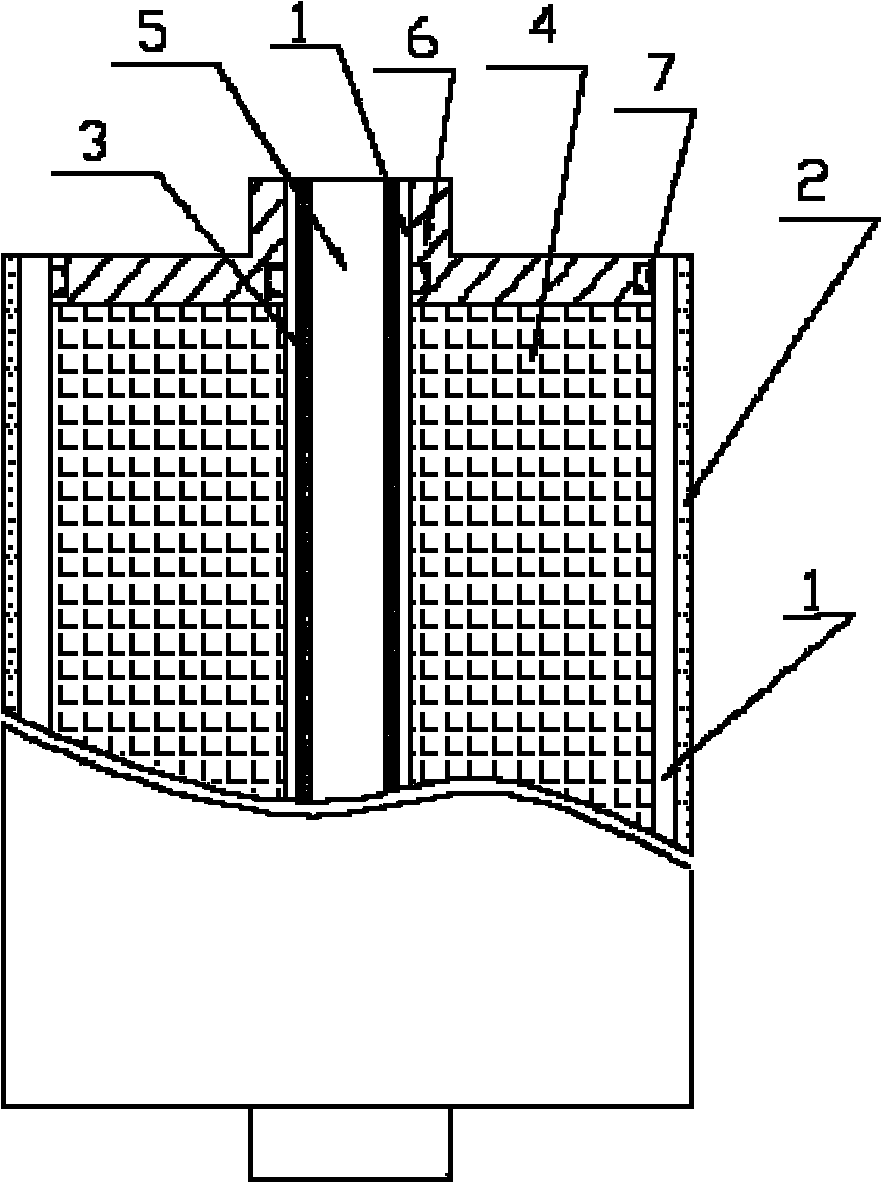
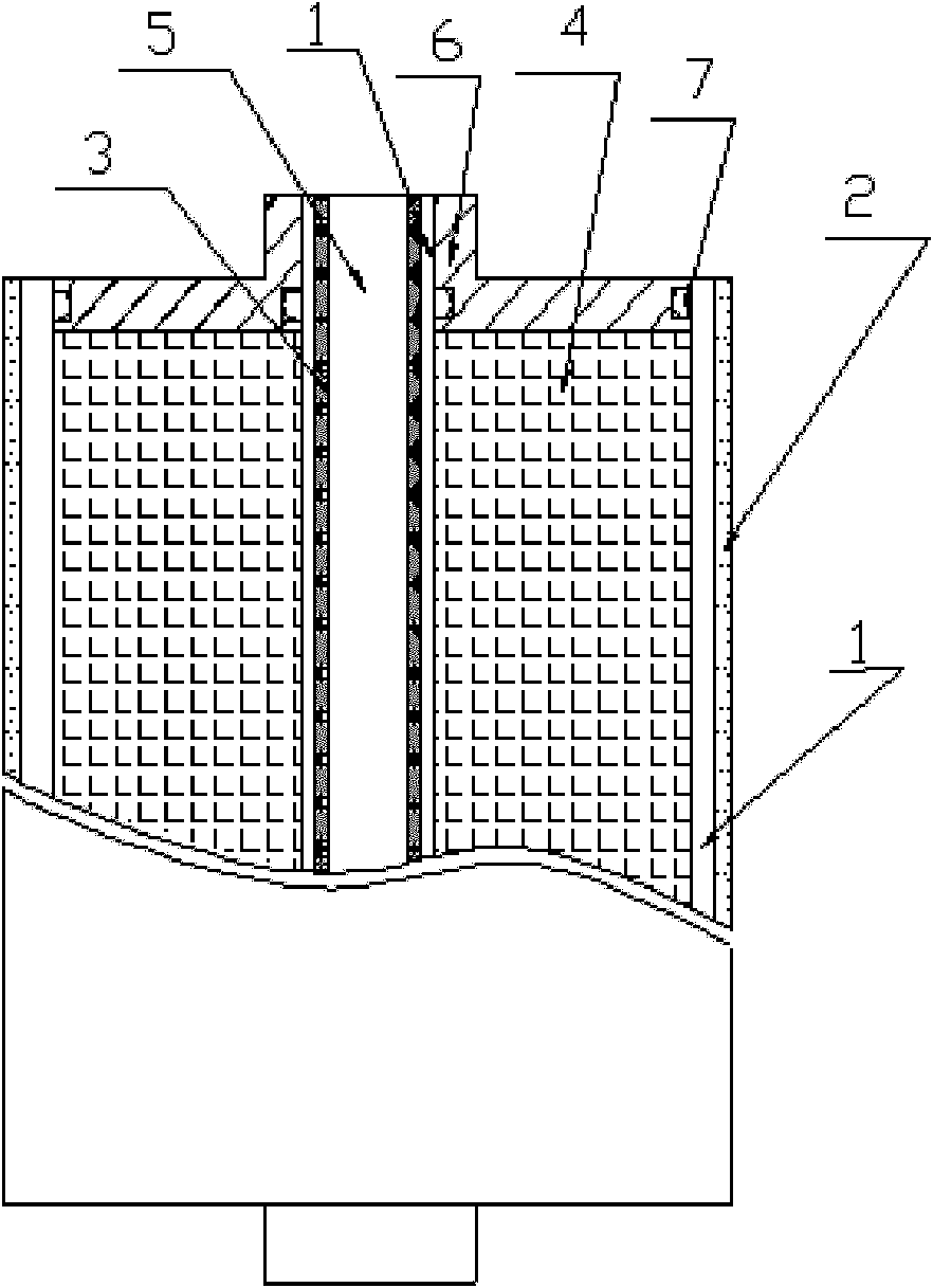
[0013] A round nickel-hydrogen battery with a design capacity of 100Ah. The structure plan is as figure 1 As shown, the pole group 4 is placed in the battery case 2 made of stainless steel. There is an insulating sleeve 1 between the pole group 4 and the battery case 2. The top cover 6 is composed of two parts: the lead-out end and the bus part, the pole group and the bus part Are connected to each other to function as confluence and conduction. The lead-out end plays a role of conduction and is also a channel for connecting the battery to the outside. The lead-out end of the top cover 6 contains a hollow channel and has a through hole to the outside; The core part is provided with a stainless steel lining part 3 with a hollow structure. There is also an insulating sleeve 1 between the pole group 4 and the lining part. There is a sealing ring 7 between the top cover 6 and the lining part 3 and the battery case 2. The shell is filled with electrolyte; the lining part 3 contains ...

Embodiment 2

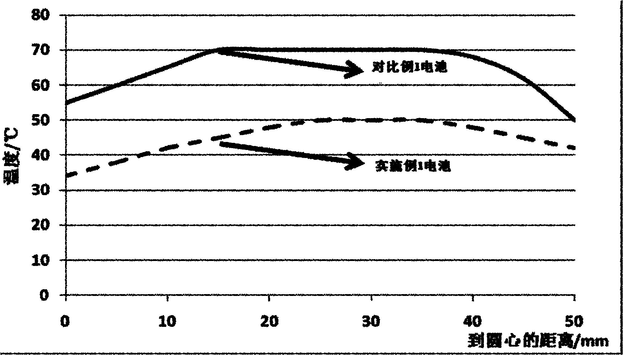
[0018] The two batteries of Example 1 and Comparative Example 1 were used to measure the internal temperature of the battery under the same conditions by implanting temperature sensors in different areas during the battery manufacturing process. After the battery was activated, a pulse charge and discharge test was performed. The test plan As follows: charge at 500A for 5S, put it aside for 5S, discharge at 500A for 5S, after 1000 cycles of continuous cycle, check the internal temperature of the battery, the result is as follows figure 2 Shown. The abscissa in the figure is the distance to the center of the circle, that is, 0-10 is the core part, and 50 is the battery surface. From figure 2 It can be seen that the maximum internal temperature of the battery in Example 1 is 50°C, while the battery in Comparative Example 1 is as high as 70°C; the internal temperature difference of the battery in Example 1 is 8°C, while the battery in Comparative Example 1 is as high as 20°C. Th...


PUM

PropertyMeasurementUnit
Diameteraaaaaaaaaa

Abstract

The invention provides a battery and a manufacturing method thereof. The battery is characterized in that an electrode group is arranged in a battery shell and is connected to a liquid-gathering part of a top cover; a sealing ring is arranged between the top cover and the shell; a lining part is arranged at the core part of the electrode group; a sealing ring is also arranged between the top cover and the lining part; the shell is filled with electrolyte; the lining part comprises a hollow channel; the leading-out end of the top cover also comprises a hollow channel and is provided with a through hole towards outside; and the hollow channel of the lining part is fully communicated with the hollow channel and through hole of the top cover. By utilizing the battery structure provided by the invention, the temperature of the battery can be lowered, and the distribution uniformity of the heat inside the battery can be improved, thus the charging and discharging efficiencies, service life and use property of the battery can be improved.

Description

Technical field [0001] The invention relates to a battery and a manufacturing method thereof. Background technique [0002] With the development of society, the requirements for battery capacity are getting higher and higher. In order to meet the high capacity requirements, the volume of the battery has also increased and the heat generated by the battery has also increased, but the internal heat of the battery is exported and dissipated more and more Difficult, because the internal heat can only be conducted in one direction, from the inside to the outside, and then to the environment. For example, a 100Ah square nickel-metal hydride battery has a volume of up to 1000cm3. It is very difficult to export the heat inside the battery. When the innermost heat is exported, it needs to pass through the conduction of each layer of pole pieces and diaphragms, and the transmission speed is slow. The internal temperature of the battery is too high, and the temperature difference between v...

Claims


Application Information

Patent Timeline
IPC IPC(8): H01M10/04H01M2/02H01M2/14H01M10/50H01M2/04H01M10/6555
CPCY02E60/10Y02P70/50
Inventor 何策衡陈风杨亚男张勇
Owner HUNAN CORUN NEW ENERGY CO LTD
Why Eureka
Try Eureka