
Method for deburring a ceramic foundry core

A technology for ceramic cores and casting molds, which is applied in ceramic molding machines, manufacturing tools, and machine tools suitable for grinding the edges of workpieces, etc. Better trim quality, reduced number of initial cracks, good reproducibility

Active Publication Date: 2011-05-11
SN DETUDE & DE CONSTR DE MOTEURS DAVIATION S N E C M A
View PDF4 Cites 4 Cited by
  • Summary
  • Abstract
  • Description
  • Claims
  • Application Information

AI Technical Summary

Problems solved by technology

However, the results were unsatisfactory as the deformation of the part due to shrinkage after sintering was incomprehensible
This shrinkage makes machining finishing difficult and difficult to automate

Method used


Image

  • Method for deburring a ceramic foundry core
  • Method for deburring a ceramic foundry core
  • Method for deburring a ceramic foundry core

Examples


Embodiment Construction

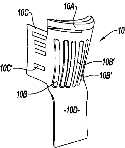
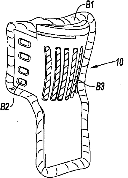
[0027] figure 1 The example components shown include core elements for a turbine hollow blade. The envelope of this element 10 has the shape of the melted-out cavity of a hollow blade. The element 10 comprises an upper part 10A which will form the slot part of the blade. The space separating this part from the central body 10B will form the upper transverse wall of the hollow blade. This central part 10B is continued downwards by a root 10D which serves to grip and secure the core in a shell mold which can be used to pour molten metal. The central part is hollowed out by longitudinal openings 10B' which will form internal partitions to define passages for cooling fluid through the blade cavities. The part 10B is continued laterally on one side by a thinner portion of the trailing edge 10C and includes an opening 10C' which will form a partition to set an outward opening along the trailing edge of the blade for emptying the cooling fluid. aisle. The core is used to be remo...


PUM


Abstract

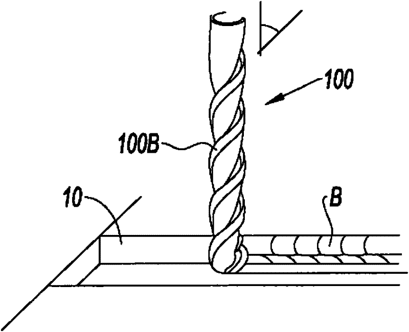
The present invention relates to a method for deburring a ceramic foundry core (10) obtained by injecting a ceramic paste, said paste including a binder having a predetermined glass transition temperature, into a mold and having at least one surface portion with a surplus of material forming a burr (B) to be eliminated. The method is characterized in that it includes the following stages: a) disposing and attaching the molded, unfired foundry core (10) onto a mounting (300); b) placing a milling tool (100), having an elongated shape with a helically cut edge, onto a tool holder; c) causing the tool to rotate around its axis and touching the milling tool to said surface portion to be deburred; and d) freezing (400) the surface portion to be deburred such that the foundry core is maintained at a temperature lower than said glass transition temperature during the deburring operation.

Description

technical field [0001] The invention relates to the finishing of components made by injection molding a ceramic slurry into a mold assembled by at least two parts along a separation line. The invention relates more particularly to the removal of burrs from the region of the separation line of the two parts. The present invention relates to ceramic cores for the manufacture of turbine hollow blades by the investment casting process. Background technique [0002] The use of so-called "ceramic" casting cores is known in specific applications where strict ranges and criteria of quality characteristics are required, such as high temperature resistance, reactive inertness, dimensional stability and good mechanical properties. Applications with such requirements are known to include: aerospace applications, for example, the manufacture of jet engine turbine blades by casting. Improvements in the molding process from so-called equiaxed casting to directionally solidified casting o...

Claims


Application Information

Patent Timeline
Patent Type & Authority Applications(China)
IPC IPC(8): B28B11/18B24B19/14
CPCB24B9/06B24B19/14B28B11/18
Inventor 克里斯蒂安·戴夫罗科特瑟奇·帕里金特丹尼尔·克驰帕特里克·瓦赫尔
Owner SN DETUDE & DE CONSTR DE MOTEURS DAVIATION S N E C M A
Learn More