Multi-shaft mortar and high-viscosity fluid stirrer for axial turbulent flow pattern multi-wire cutting machine

A multi-wire cutting machine and agitator technology, which is used in mixers with rotary stirring devices, mixers, liquid and solid mixing, etc. Flexible and reasonable structure design effect

Inactive Publication Date: 2011-10-26
XIAN HUAJING ELECTRONICS TECH
View PDF9 Cites 0 Cited by
  • Summary
  • Abstract
  • Description
  • Claims
  • Application Information

AI Technical Summary

Problems solved by technology

In the actual production process, in order to increase the production output of the multi-wire cutting machine, it is necessary to install multiple mortar mixing tanks, which puts forward new requirements for factory buildings, and various costs will increase accordingly
[0003] In addition, in the chemical industry, daily necessities industry, mining industry and other industrial fields, there is also an urgent need to research and develop a fluid agitator that can uniformly stir high-solid-liquid ratio and high-viscosity fluids, especially in the flotation process in the mining industry. The different particle sizes of the solids put in at one time can easily cause the agitator to be stuck. How to prevent large solids from entering the agitator and blocking the agitator, people have to use various screens to achieve

Method used


Image

  • Multi-shaft mortar and high-viscosity fluid stirrer for axial turbulent flow pattern multi-wire cutting machine
  • Multi-shaft mortar and high-viscosity fluid stirrer for axial turbulent flow pattern multi-wire cutting machine
  • Multi-shaft mortar and high-viscosity fluid stirrer for axial turbulent flow pattern multi-wire cutting machine

Examples


Embodiment 1

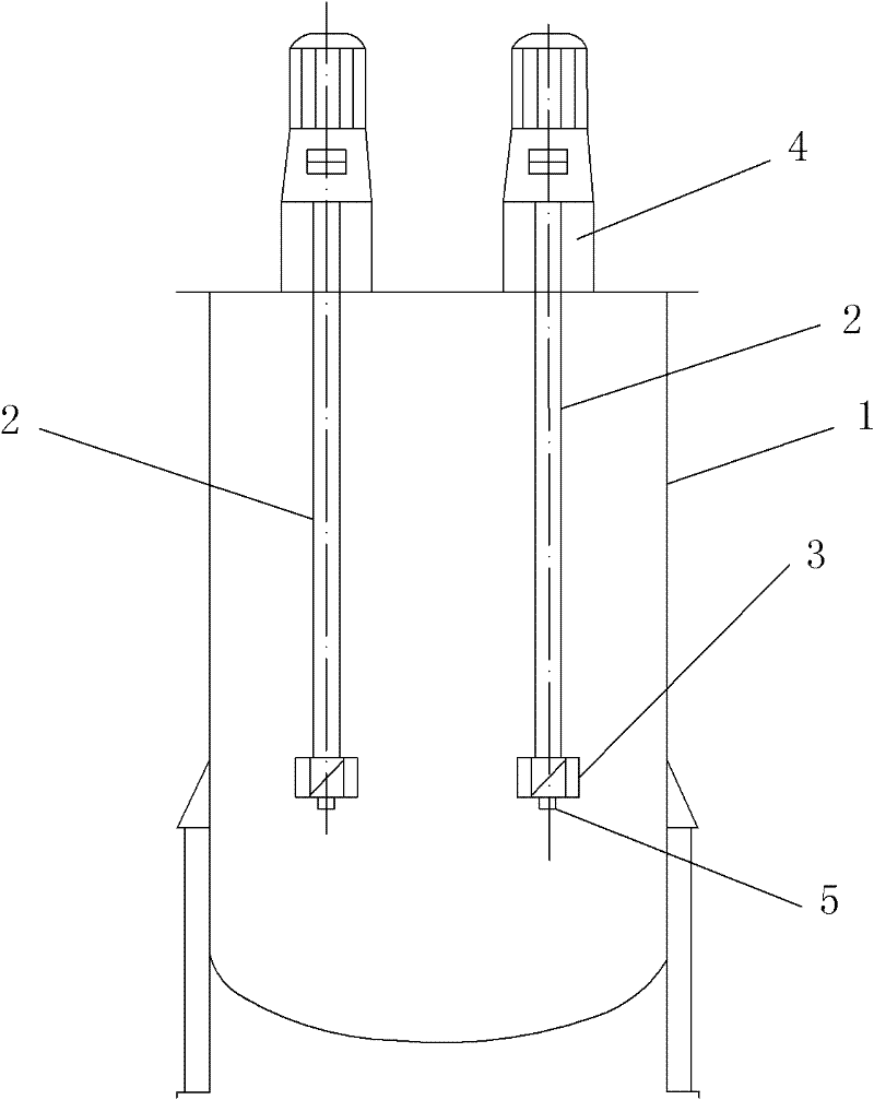
[0037] like figure 1 , figure 2 , image 3 and Figure 4 As shown, the present invention includes a plurality of single-shaft stirring units arranged in the stirring tank body 1 along the circumferential direction, and the structures of the plurality of single-shaft stirring units are the same.

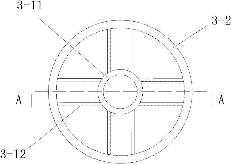
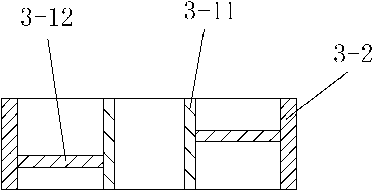
[0038] The single-shaft stirring unit includes a stirring shaft 2 installed in the stirring tank body 1 and arranged vertically, a stirring assembly 3 that continuously rotates with the stirring shaft 2 and uniformly stirs the materials in the stirring tank body 1, and A driving mechanism installed above the stirring shaft 2 and driving the stirring shaft 2 to continuously rotate, the driving mechanism is connected to the stirring shaft 2 through a transmission mechanism. The stirring assembly 3 is coaxially installed on the bottom end of the stirring shaft 2, and the stirring assembly 3 includes an impeller 3 that drives the material along the inner wall of the mixing tank body 1...

Embodiment 2

[0056] like Figure 5 As shown, in this embodiment, the difference from Embodiment 1 is that the number of the single-shaft stirring units is three, and the dimensions and installation heights of the three single-shaft stirring units are the same. In this embodiment, the structure, installation method and working principle of other parts are the same as those in Embodiment 1.

Embodiment 3

[0058] like Image 6 and Figure 7 As shown, in this embodiment, the difference from Example 1 is that: the number of the uniaxial stirring units is 4, and the number of the two uniaxial stirring units opposite to each other among the 4 uniaxial stirring units The dimensions and installation heights are the same, and the effective lengths of the stirring shafts 2 in two adjacent single-shaft stirring units are different, so the stirring assemblies 3 of the four single-shaft stirring units are not arranged at the same height. During actual processing and production, the dimensions and installation heights of the four single-shaft stirring units can also be adjusted to be consistent. In this embodiment, the structure, installation method and working principle of other parts are the same as those in Embodiment 1.


PUM

PropertyMeasurementUnit
diameteraaaaaaaaaa
heightaaaaaaaaaa

Abstract

The invention discloses a multi-shaft mortar and high-viscosity fluid stirrer for an axial turbulent flow pattern multi-wire cutting machine, comprising a plurality of single shaft stirring units which have the same structure and are uniformly arranged in a pot body of a stirring pot along the circumferential direction, each single shaft stirring unit comprises a stirring shaft arranged vertically, a stirring assembly and a driving mechanism, the stirring assemblies are coaxially installed at the bottom end of the stirring shaft and comprise impellers and short flow division tubes, the short flow division tubes are used for restricting a material flow direction to an axial movement along the stirring shaft, the impellers and the short flow division tubes are assembled into the stirring assembly which drives the material needed to be mixed and stirred to do an axial turbulent flow motion, the impellers are coaxially installed at the bottom end of the stirring shaft, and the short flow division tubes are coaxially sleeved at the outer sides of the impellers. The multi-shaft mortar and high-viscosity fluid stirrer has the advantages of simplicity in structure, high stirring ability, small shearing force, high dispersing power and high effect, and can be used for solving the problem that silicon carbide is broken due to the shearing force during the high-speed stirring of various traditional stirrers. Moreover, a stuck phenomenon is difficult to generate.

Description

technical field [0001] The invention relates to a multi-shaft agitator, in particular to a multi-shaft agitator for axial turbulent flow type multi-wire cutting machine mortar and high-viscosity fluid. Background technique [0002] The cutting mortar for multi-wire cutting machine is a high liquid-solid ratio of up to 1:0.95, that is, a high-viscosity suspension, and the solid silicon carbide of the suspension must have good dispersion during actual cutting. At the same time, the solid silicon carbide is very uniformly suspended in the cutting fluid to form a cutting mortar. And during the stirring process of the slurry, it is necessary to avoid violent stirring to cause the silicon carbide particles to be sheared and broken to affect their cutting performance. In the traditional mortar mixing tank for multi-wire cutting machine, the agitator is mostly a paddle or frame agitator. During the mixing process, the fluid flow pattern is generally radial movement, and the fluid f...

Claims


Application Information

Patent Timeline
Patent Type & Authority Patents(China)
IPC IPC(8): B01F7/22B01F7/18B01F3/14B01F27/91B01F23/57
Inventor 杨国农贺鹏杨易贺青陈波
Owner XIAN HUAJING ELECTRONICS TECH
Why Eureka
Try Eureka