Laser double-side synchronous welding system with skin-skeleton structure
A skeleton structure and welding system technology, applied in the field of laser double-sided synchronous welding system, can solve the problems of inconvenient adjustment of laser incident angle, limitation of defocusing amount during welding, ablation of spectroscopic mirror, etc., so as to avoid limited selection and convenient adjustment Flexible, Simple Effects
- Summary
- Abstract
- Description
- Claims
- Application Information
AI Technical Summary
Problems solved by technology
Method used
Image
Examples
specific Embodiment approach 1
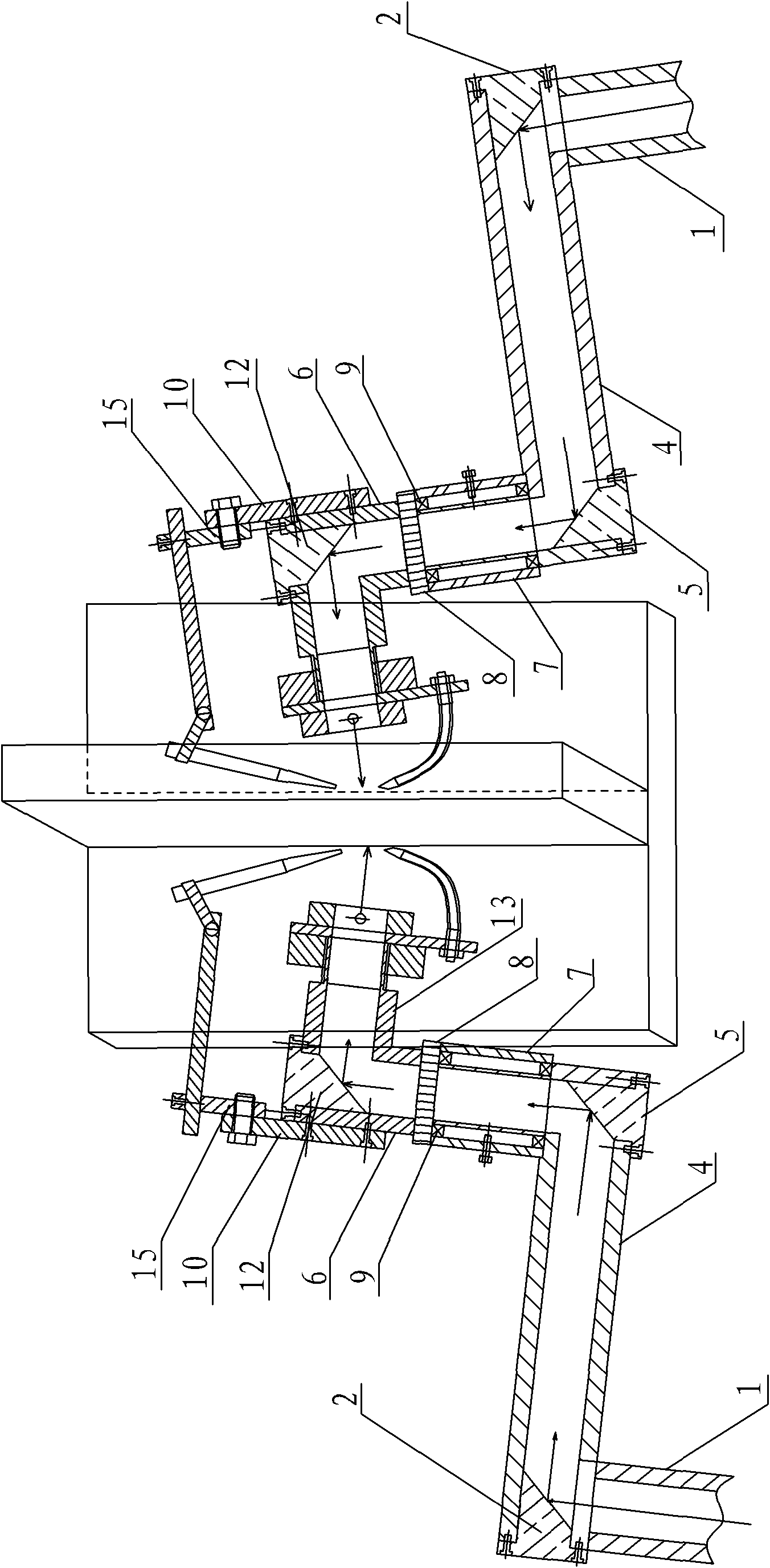
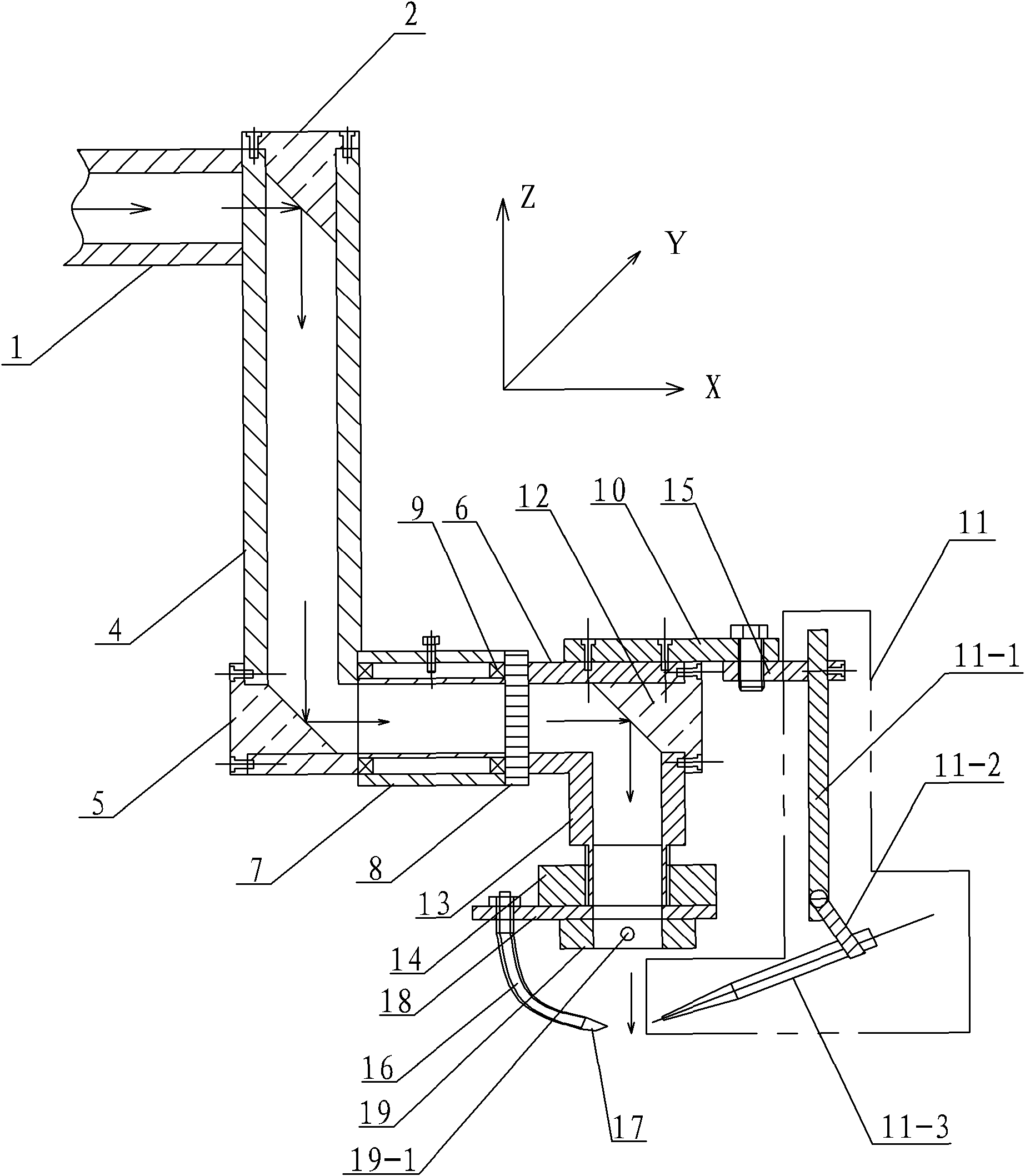
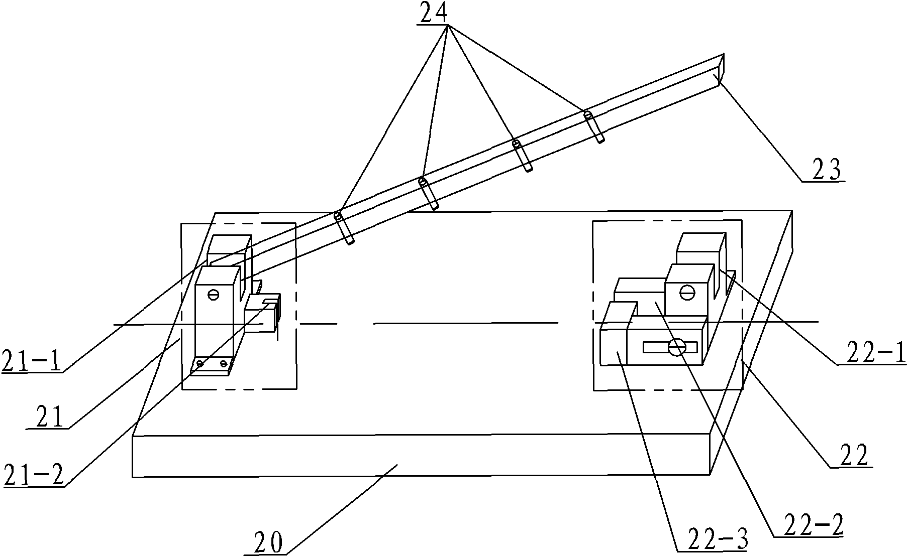
[0009] Specific implementation mode one: combine figure 1 and figure 2 Describe this embodiment, the laser double-sided synchronous welding system of the skin-skeleton structure of this embodiment includes two welding devices, and each welding device includes a first tube 1, a first reflector 2, and a second tube 4 And the second mirror 5, each welding device also includes a third tube 6, a sleeve 7, a scale ring 8, at least one bearing 9, a first connecting plate 10, a wire feeding device 11, a focusing mirror 12, a fourth tube Barrel 13, height adjustment block 14 with internal thread, second connecting plate 15, flexible pipe 16, nozzle 17, third connecting plate 18 and air knife 19, the laser double-sided synchronous welding system also includes the test piece to be welded Clamping device, two welding devices are arranged opposite to each other, and the two welding devices are arranged above the clamping device of the test piece to be welded, the skin-skeleton is clamped...
specific Embodiment approach 2
[0014] Specific implementation mode two: combination figure 1 and figure 2 Describe this embodiment, the wire feeding device 11 of this embodiment includes a wire feeding rod 11-1, a clamping rod 11-2 and a wire feeding nozzle 11-3, the wire feeding rod 11-1 is arranged on the second connecting plate 15, The clamping rod 11-2 is rotatably mounted on the wire feeding rod 11-1, and the wire feeding nozzle 11-3 is clamped on the clamping rod 11-2. In this way, by adjusting the relative positions of the first connecting plate 10, the second connecting plate 15, the wire feeding rod 11-1 and the clamping rod 11-2, the wire feeding nozzle 11-3 can be adjusted in the three directions of X, Y and Z. The precise adjustment of the wire feeding rod 11-1, the clamping rod 11-2 and the wire feeding nozzle 11-3 will finally realize the precise distribution of the relative positions. The wire feeding nozzle 11-3 is connected to the wire feeding machine through the wire feeding guide tube. ...
specific Embodiment approach 3
[0015] Specific implementation mode three: combination figure 1 and figure 2 The present embodiment will be described. The fourth tube 13 and the third tube 6 of the present embodiment are integrally formed. Such setting facilitates installation and guarantees accuracy. Other compositions and connections are the same as those in Embodiment 1 or Embodiment 2.
PUM
 Abstract
Description
Claims
Application Information
 - R&D
- Intellectual Property
- Life Sciences
- Materials
- Tech Scout
- Unparalleled Data Quality
- Higher Quality Content
- 60% Fewer Hallucinations
Browse by: Latest US Patents, China's latest patents, Technical Efficacy Thesaurus, Application Domain, Technology Topic, Popular Technical Reports.
© 2025 PatSnap. All rights reserved.Legal|Privacy policy|Modern Slavery Act Transparency Statement|Sitemap|About US| Contact US: help@patsnap.com


