External thermal insulation structure of electrolytic cell

An external thermal insulation and electrolytic cell technology, which is applied in the field of aluminum electrolytic cells, can solve the problems of unfeasible inner lining structure, and achieve the effects of saving cost and time, facilitating thermal insulation strength and facilitating adjustment.

Active Publication Date: 2011-05-18
ZUNYI ALUMINUM
View PDF4 Cites 13 Cited by
  • Summary
  • Abstract
  • Description
  • Claims
  • Application Information

AI Technical Summary

Problems solved by technology

However, it is not feasible to change the lining structure for the electrolyzer that has been built and put into production.

Method used


Image

  • External thermal insulation structure of electrolytic cell
  • External thermal insulation structure of electrolytic cell
  • External thermal insulation structure of electrolytic cell

Examples


Embodiment 1

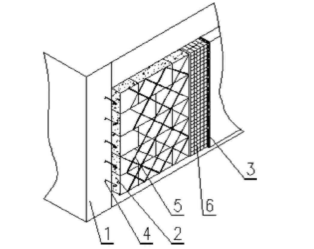
[0017] Embodiment 1: as figure 2 As shown, the insulation layer 2 is laid outside the electrolytic cell shell 1, and the insulation layer 2 can adopt a plate-like hard and semi-hard insulation material layer, such as a hydrophobic expanded perlite insulation layer, insulation cotton board, etc. When the thermal insulation material layer is used as the thermal insulation layer, an expansion joint is left between two hard thermal insulation material layers, and a flexible thermal insulation material layer is filled in the expansion joint. After the insulation layer 2 is placed, the insulation layer 2 is fixed by the hook nails 4 of the fixing parts welded on the electrolytic cell shell 1. The outside of the insulation layer 2 is fastened with galvanized iron wire 5 and galvanized wire mesh 6 and the hook nails 4. Adopt plastering structure to make protective layer 3 on 6, also can not make protective layer 3.

Embodiment 2

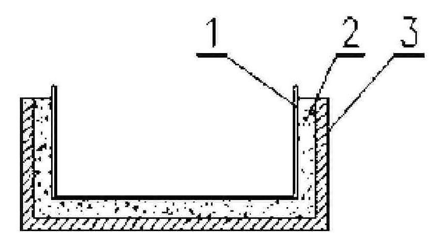
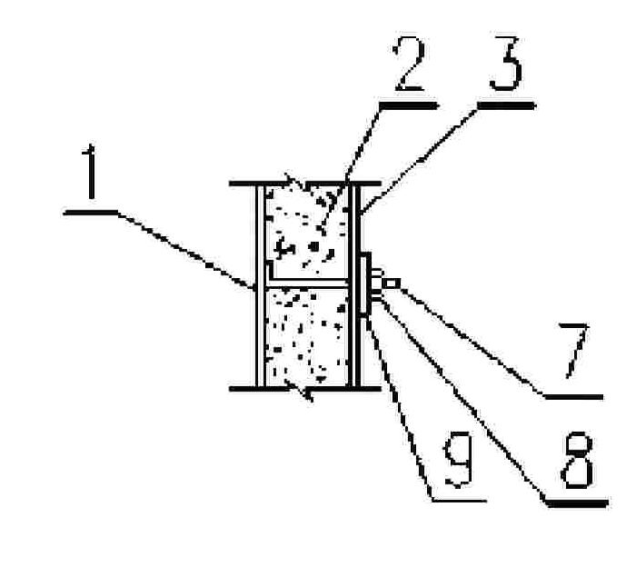
[0018] Embodiment 2: as figure 1 and image 3 As shown, an insulation layer 2 is laid outside the electrolytic cell shell 1. The insulation layer 2 can be made of composite silicate felt, microporous calcium silicate products, rock wool and slag wool felt, board products, ultra-fine glass wool products, poly Urethane foam plastics, hydrophobic expanded perlite products, cement expanded perlite products, aluminum silicate products, foam glass, etc., the insulation layer 2 can be one layer, two layers or more than two layers, and each layer can use the same or Different insulation materials, the protective layer 3 laid outside the thermal insulation layer 2 can be a metal or aluminum foil glass fiber reinforced plastic sheet, the thermal insulation layer 2 and the protective layer 3 are connected by the fixing piece pin 7 welded on the electrolytic cell shell 1, and the nut 8 and the gasket 9 fixed.

Embodiment 3

[0019] Embodiment 3: as figure 1 and Figure 4 As shown, a thermal insulation device is laid outside the electrolytic cell shell 1. The thermal insulation device includes a thermal insulation layer 2 and a protective layer 3. The area covered by the thermal insulation device on the electrolytic cell shell 1 is 1% to 100%, and the protective layer 3 is a composite The protective layer, the metal protective layer or the aluminum foil glass fiber reinforced plastic sheet, is connected and fixed by the fixing member pin 10 welded on the electrolytic cell shell 1 and the self-locking plate 11 to fix the insulating layer 2 and the protective layer 3 . A support member can be erected on the electrolytic cell shell 1 to support the heat insulation layer 2 .

[0020] The protective layer 3 can be a metal protective layer, a composite protective layer or a plastering protective layer: the metal protective layer can be galvanized thin steel plate, galvanized iron sheet, aluminum alloy p...


PUM


Abstract

The invention discloses an external thermal insulation structure of an electrolytic cell, comprising the shell of the electrolytic cell, a thermal insulating layer and a protective layer, wherein the thermal insulating layer is arranged outside the shell of the aluminium electrolytic cell; and the protective layer can be arranged outside the thermal insulating layer optionally. A thermal insulation structure outside the aluminium electrolytic cell can be a full-thermal insulation structure outside the shell of the aluminium electrolytic cell and also can be a thermal insulation structure in a local range. The thermal insulation structure outside the aluminium electrolytic cell can be a fixed thermal insulation structure or a detachable thermal insulation structure, thus the problem of heat balance of the electrolytic cell can be solved under the condition that the stability of the electrolytic cell is strengthened, the electrode distance is reduced and the voltage is lowered; the normal working requirements of the electrolytic cell are met; and in particular, the cost and time can be greatly saved when the heat balance of the existing electrolytic cell is maintained.

Description

technical field [0001] The invention relates to an aluminum electrolytic cell, in particular to an external thermal insulation structure of an aluminum electrolytic cell. Background technique [0002] In the aluminum electrolysis industry, in order to maintain the heat balance and energy balance in the electrolysis production, an insulation layer is usually provided at the bottom of the aluminum electrolysis cell, and above the insulation layer is a layer of anti-seepage material layer, and cathode carbon blocks are built on the anti-seepage material layer. The existing electrolytic cell technology operates under high pole distance and high voltage, and more attention is paid to the heat dissipation of the electrolytic cell, so no insulation measures are taken; but with the strengthening of the stability of the aluminum electrolytic cell, the reduction of the pole distance and the voltage Reduced, the electrolyzer will have the problem of reduced heat income and increased he...

Claims


Application Information

Patent Timeline
Patent Type & Authority Applications(China)
IPC IPC(8): C25C3/10
Inventor 黄俊
Owner ZUNYI ALUMINUM
Why Eureka
Try Eureka