Energy-saving device and energy-saving method for low-calorific-value fuel gas heating furnace

An energy-saving device and fuel gas technology, applied in the direction of combustion methods, furnace control devices, lighting and heating equipment, etc., can solve the problems of reducing the exhaust gas temperature of tube furnaces, the exhaust gas temperature cannot be further reduced, and the efficiency is low, and achieve Reduced heat transfer area, high reliability, and reduced flue gas volume

Pending Publication Date: 2020-04-07
LUOYANG MINGYUAN PETROCHEM IND TECH
View PDF0 Cites 0 Cited by
  • Summary
  • Abstract
  • Description
  • Claims
  • Application Information

AI Technical Summary

Problems solved by technology

[0002] Tube furnace is one of the main process equipment in petroleum refining, petrochemical and chemical, chemical fiber and other industries, and it is also a key energy-consuming equipment in petroleum refining, petrochemical and chemical, chemical fiber and other industries. 50-70% of the energy consumption, reducing the exhaust gas temperature of the tube furnace and recovering the waste heat of the flue gas is one of the main technical means to improve the efficiency of the tube furnace and reduce the energy consumption of the device; at present, petroleum refining, petrochemical and chemical, chemical fiber and other industries Based on energy saving and process factors, it is generally preferred to use the by-product gas of the device as the fuel for the heating furnace. Some of the by-product fuel gas has a lower calorific value, such as the main fuel of the hydrogen production reformer in the hydrogen production device in the petrochemical industry. Tail gas (also known as pressure swing adsorption desorption gas) has a calorific value of 2000 kcal / m3 (1600 kcal / kg), and non-flammable components account for more than 60% of the components, of which only CO 2 The content of hydrogen production exceeds 50%. The hydrogen production tail gas provides more than 65% of the heat of the reformer of the hydrogen production device as fuel, and the insufficient part is provided by other fuels. Due to the low calorific value of the fuel gas and the large amount of fuel, the amount of flue gas in the heating furnace is different from that of the fuel. The mass ratio of the air volume is more than 1.3, while the mass ratio of the flue gas volume to the air volume of the heating furnace of other equipment, such as reforming, atmospheric and vacuum equipment, is generally about 1.05. Therefore, the exhaust gas of the heating furnace of the hydrogen production equipment The main key factor that the temperature cannot be further reduced is the heat balance problem, that is, the heat released by the temperature of the flue gas is limited by the heat absorbed by the air, which leads to the fact that the exhaust gas temperature cannot be further reduced. At present, the efficiency of the hydrogen production reformer is low, and the exhaust gas temperature Most of them are at 140-200°C. The existing technology cannot solve the heat balance problem of this kind of heating furnace. The exhaust gas temperature is high and the furnace efficiency is low.

Method used


Image

  • Energy-saving device and energy-saving method for low-calorific-value fuel gas heating furnace
  • Energy-saving device and energy-saving method for low-calorific-value fuel gas heating furnace

Examples


Embodiment 1

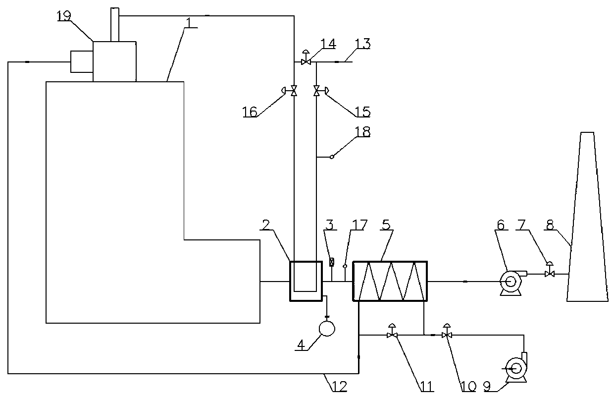
[0026] As shown in the figure, a low calorific value fuel gas heating furnace energy-saving device includes a heating furnace 1, a burner 18 arranged on the top of the heating furnace 1, and a fuel gas preheater 2 arranged at the flue gas outlet of the heating furnace 1. The fuel gas preheater 2 is provided with a fuel gas inlet pipeline and a fuel gas outlet pipeline, and a fuel gas auxiliary line pipeline is also provided between the fuel gas inlet pipeline and the fuel gas outlet pipeline, and the fuel gas auxiliary line The line pipeline directly sends the fuel from the fuel gas inlet pipeline to the burner 19, and also includes an air preheater 5 arranged at the flue gas outlet of the fuel gas preheater 2, and the flue gas outlet of the air preheater 5 is provided with A flue gas induced draft fan 6, the outlet of the flue gas induced draft fan 6 is provided with a flue gas discharge chimney 8, the fuel gas outlet pipeline is connected with the burner 19, the fuel gas inle...

Embodiment 2

[0034] The difference between embodiment 2 and embodiment 1 is that the detection element for avoiding flue gas dew point corrosion is arranged on the outer wall surface of the heat exchange element of the fuel gas preheater 1 and is also provided with a wall surface thermometer 4, and a wall surface thermometer 4 When the trigger temperature is lower than the temperature limit value, the valve 14 of the secondary pipeline of the fuel burner is triggered to open. The temperature limit value is the flue gas dew point temperature T~T+50°C. At the same time, the fuel gas inlet valve 15 and the fuel gas outlet valve 16 are closed. The fuel gas enters the heating furnace 1 through the fuel gas sub-line valve 14 to burn, so as to avoid dew point corrosion failure of the heat exchange element of the fuel gas preheater 2, resulting in fuel gas leakage, and fuel leakage of the fuel gas preheater caused by flue gas dew point corrosion Surveillance, prevention and treatment.

Embodiment 3

[0036] In embodiment 3, the fuel gas temperature measuring instrument 18, the flue gas temperature measuring instrument 17 and the wall surface thermometer 4 are set at the same time, and the gas leakage alarm device 3 is set at the same time, which plays the role of triple protection at the same time, avoiding fuel gas preheating. The dew point corrosion failure of the heat exchange element of Heater 2 leads to fuel gas leakage, which is used for the monitoring, prevention and disposal of fuel gas preheater fuel leakage caused by flue gas dew point corrosion.


PUM


Abstract

The invention belongs to the technical field of petrochemical engineering. The invention particularly discloses an energy-saving device and energy-saving method for a low-calorific-value fuel gas heating furnace. The device comprises a heating furnace, a combustor at the top of the heating furnace, a fuel gas preheater arranged at a flue gas outlet of the heating furnace, wherein a fuel gas inletpipeline and a fuel gas outlet pipeline are arranged on the fuel gas preheater, a fuel gas subline pipeline is also arranged between the fuel gas inlet pipeline and the fuel gas outlet pipeline and fuel from the fuel gas inlet pipeline is directly conveyed into the combustor by the fuel gas auxiliary pipeline, an air preheater arranged at a flue gas outlet of the fuel gas preheater, a flue gas induced fan arranged at the flue gas outlet of the fuel gas preheater, and a flue gas discharging chimney arranged at an induced fan outlet. Fuel gas is heated through flue gas so that the fuel consumption is reduced, the flue gas amount of the device is reduced, reduction of the exhaust gas temperature is facilitated, and the economical efficiency of the device is improved.

Description

technical field [0001] The invention belongs to the technical field of petrochemical industry, and in particular relates to an energy-saving device and an energy-saving method for a low calorific value fuel gas heating furnace. Background technique [0002] Tube furnace is one of the main process equipment in petroleum refining, petrochemical and chemical, chemical fiber and other industries, and it is also a key energy-consuming equipment in petroleum refining, petrochemical and chemical, chemical fiber and other industries. 50-70% of the energy consumption, reducing the exhaust gas temperature of the tube furnace and recovering the waste heat of the flue gas is one of the main technical means to improve the efficiency of the tube furnace and reduce the energy consumption of the device; at present, petroleum refining, petrochemical and chemical, chemical fiber and other industries Based on energy saving and process factors, it is generally preferred to use the by-product ga...

Claims


Application Information

Patent Timeline
Patent Type & Authority Applications(China)
IPC IPC(8): F27D17/00F27D19/00F23L15/00
CPCF23L15/00F27D17/004F27D19/00F27D2019/0028Y02E20/34Y02P20/10
Inventor 程高锋唐海宽王瑞星
Owner LUOYANG MINGYUAN PETROCHEM IND TECH
Why Eureka
Try Eureka