Cellular pneumatic driving wheel power machine

A power machine and driving wheel technology, applied in the field of grid-type pneumatic driving wheel power machine, can solve the problems of power consumption, waste of resources, lower utilization efficiency, etc., and achieve the effects of increasing output power, occupying less space, and high work efficiency

Inactive Publication Date: 2012-08-15
李玉森
View PDF0 Cites 0 Cited by
  • Summary
  • Abstract
  • Description
  • Claims
  • Application Information

AI Technical Summary

Problems solved by technology

Traditional power equipment consumes a lot of power when doing work. For example, in a 2-stroke or 4-stroke work process of a fuel engine, only one stroke does work, and the rest of the strokes consume power; The loss is large, which reduces the utilization efficiency
3. Non-environmental protection
For example, a fuel engine will produce harmful gases due to combustion during operation, and improper disposal of waste batteries will also have an impact on the environment; 4. The structure of the power unit cannot be adjusted according to the requirements of output power, resulting in a certain waste of resources; 5. Energy It is a non-renewable fossil fuel and cannot be recycled; 6. The equipment is heavy and bulky; 7. It is not easy to expand

Method used


Image

  • Cellular pneumatic driving wheel power machine
  • Cellular pneumatic driving wheel power machine
  • Cellular pneumatic driving wheel power machine

Examples


Embodiment Construction

[0029] The present invention will be further described below in conjunction with the drawings and embodiments.

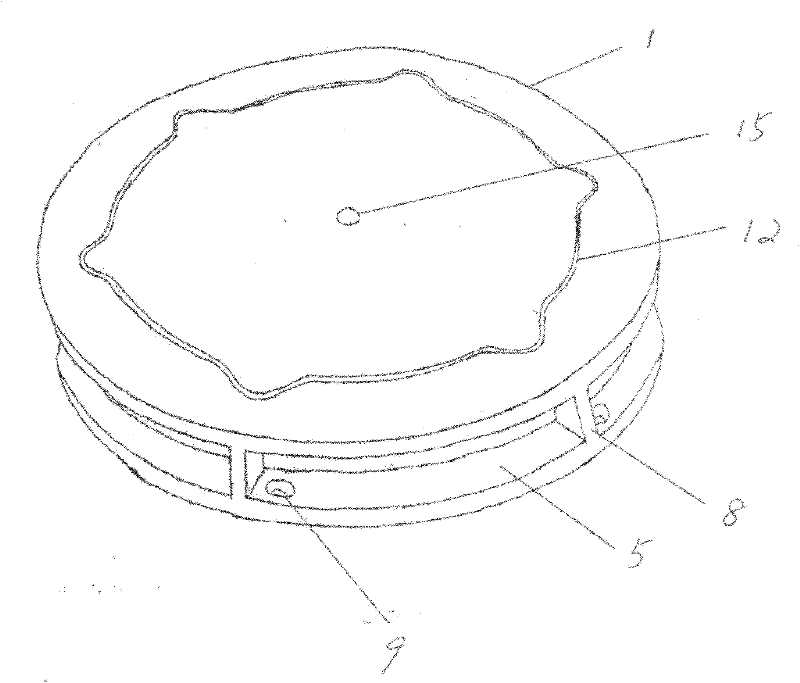
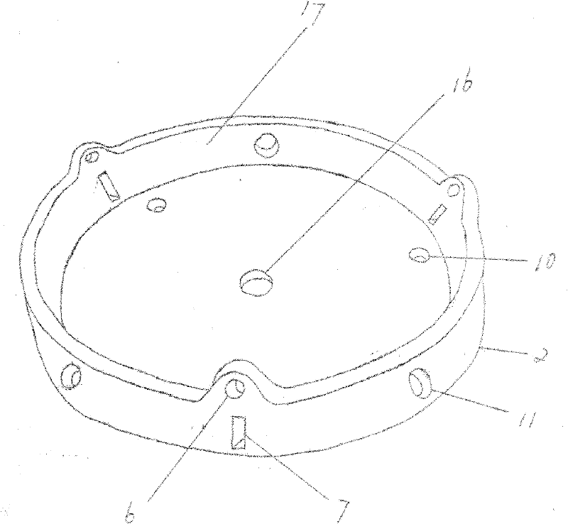
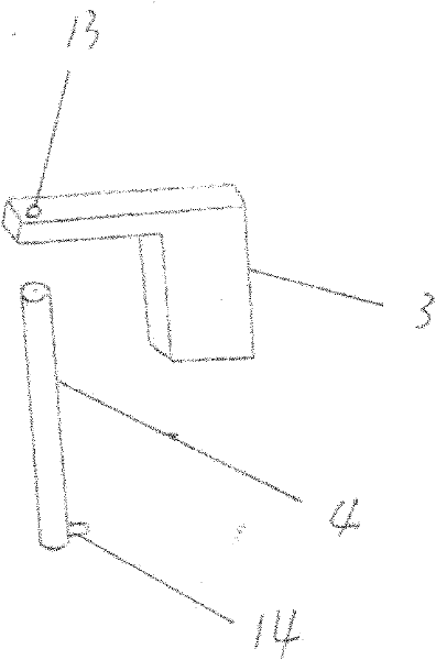
[0030] The invention uses the pressure air source to drive the driving unit to rotate, thereby driving the output shaft to rotate, and completing the power output. The number and size of drive units can be flexibly adjusted according to the required power. Each drive unit includes a rotating wheel 1, a base 2 and an air chamber sealed sliding partition 3, such as figure 1 , figure 2 , image 3 , Figure 4 , Figure 5 Shown. The rotating wheel 1 is provided with a plurality of partitioned independent air grooves 5 separated by the air groove 8; an air inlet 9 is provided at one end of each partitioned independent air groove 5, and the air inlet 9 is opened in the rotating wheel The bottom surface of 1. At the same time, the upper bottom surface of the rotating wheel 1 is provided with an annular guide groove 12 centered on the center of the circle. The annular guide ...


PUM


Abstract

The invention relates to a cellular pneumatic driving wheel power machine which has the advantages of simple structure, convenience of use, energy saving, high efficiency and environmental protection. The cellular pneumatic driving wheel power machine comprises at least one drive unit installed on an output shaft, wherein the drive unit comprises a rotary wheel, the rotary wheel is installed in afixed base and is connected with the output shaft, a plurality of independent partition type gas drive devices formed with the inner wall of the base are arranged on the side surface of the rotary wheel, annular guide grooves are arranged at the top of the rotary wheel, one of the annular guide grooves and two annular guide grooves corresponding to gas groove partitions of two partition type gas drive devices adjacent to the annular guide groove protrude outwards along the longitudinal direction, each partition type gas drive device is provided with at least one regulating device, the regulating device is connected between the base and the rotary wheel, and one ends of the regulating devices are also installed in the annular guide grooves.

Description

Technical field [0001] The invention relates to a grid type pneumatic wheel driving power machine. Background technique [0002] The main forms of current common power output are: one is to output power through a fuel engine, the other is to output power through an electric motor, and the other is to output power through a steam turbine. Their characteristics are: 1. The equipment structure is complex. For example, a fuel engine needs a cooling cycle system, an oil circuit system, etc., while an electric motor needs a circuit or battery charging and discharging system, which will increase the cost of the product; 2. The efficiency is not very high. Traditional power equipment consumes a lot of power when doing work. For example, a fuel engine has only one stroke during a 2-stroke or 4-stroke process, and the rest of the strokes consume power. Another example is that the blades of the steam turbine cannot be sealed, and the energy The loss is large and the utilization efficiency...

Claims


Application Information

Patent Timeline
Patent Type & Authority Patents(China)
IPC IPC(8): F01C1/356F01C20/10F01C21/18
Inventor 李玉森李诺
Owner 李玉森
Why Eureka
Try Eureka