String-type wind wheels and magnetic levitation string-type windmill

A technology of magnetic levitation and wind wheel, which is applied in the direction of wind power generators, wind power generation, wind power generators, etc. at right angles to the wind direction, can solve problems such as the contradiction between efficiency and startability, the impact on aerodynamic efficiency, and the increase in cost, so as to reduce the installed cost and increase the cost. Sweeping area, good benefit effect

Inactive Publication Date: 2011-05-18
李永平
View PDF0 Cites 7 Cited by
  • Summary
  • Abstract
  • Description
  • Claims
  • Application Information

AI Technical Summary

Problems solved by technology

Among them, although the Φ type, H type, △ type, and ◇ type have the advantage of simple blade manufacturing, they are difficult to self-start when there are only 2 to 3 blades, but this form of 2 to 3 blades is also aerodynamic. High-efficiency form, so there is a contradiction between efficiency and start-up of the Darrieus wind wheel
For a long time, in order to solve the problem of self-starting, the method adopted is multi-blades, or adding a starting device, or combining with a resistance-type wind wheel, which in turn brings an increase in cost and affects aerodynamic efficiency

Method used


Image

  • String-type wind wheels and magnetic levitation string-type windmill
  • String-type wind wheels and magnetic levitation string-type windmill
  • String-type wind wheels and magnetic levitation string-type windmill

Examples


example 1

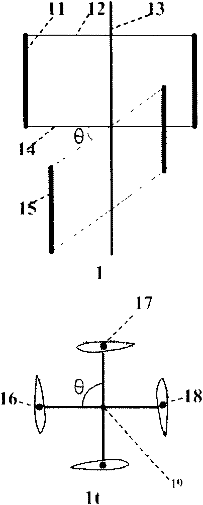
[0039] Example 1: A series of wind rotors composed of two H-type 2-blade wind rotors.

[0040] as attached figure 1 shown. In the figure: 11 is the blade of the upper single wind rotor, 12 is the upper horizontal support arm of the upper single wind rotor blade, 13 is the hub or rotating shaft of the string type wind rotor, and 14 is the lower part of the upper single wind rotor blade. Horizontal support arm, 15 is the fan blade of lower layer single wind wheel.

[0041] The string type wind wheel is composed of two single wind wheels up and down. Each single wind rotor is in the shape of "middle", each has 2 straight blades, the blade support arm is horizontally supported, the lower horizontal support arm of the upper single wind rotor and the upper horizontal support arm of the lower single wind rotor form a Cross-shaped, they are on the same horizontal plane, and the θ angle in the vertical projection of the preferred configuration is 360 / (2+2)=90 degrees.

example 2

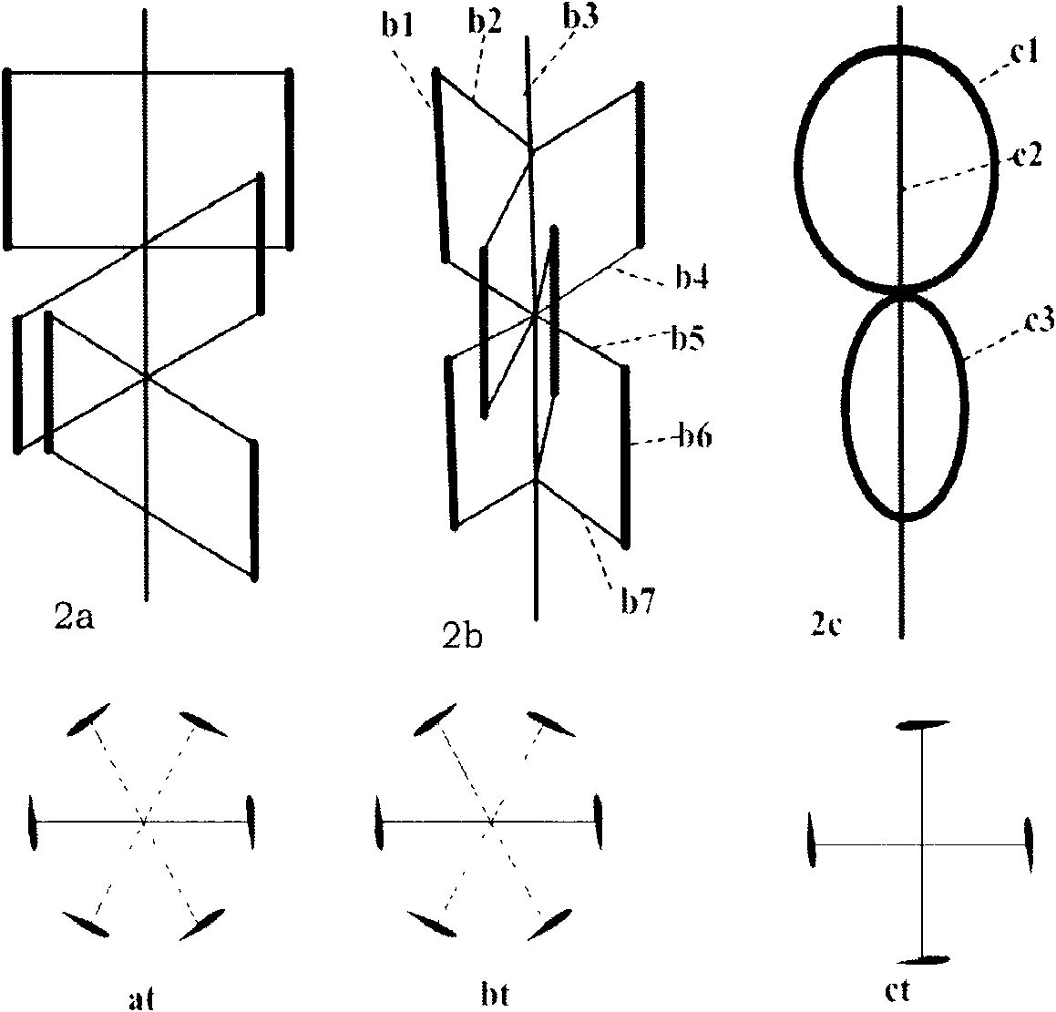
[0042] Example 2 is a series wind rotor composed of two three-bladed H-type wind rotors.

[0043] as attached figure 2 Shown in 2b. In the picture:

[0044] b1. The blades of the upper single wind rotor, b2: the upper horizontal support arm of the upper single wind rotor, b3: the central axis of the wind rotor, b4: the lower horizontal support arm of the upper single wind rotor, b5: the upper horizontal support of the lower single wind rotor Arm, b6: the blades of the lower single wind rotor, b7: the lower horizontal support arm of the lower single wind rotor

[0045] Each layer of single wind rotor is composed of a 3-blade H-shaped turbine, the blade support arm adopts horizontal support, the lower horizontal support arm of the upper unit and the upper horizontal support arm of the lower unit constitute type, they are in the same horizontal plane, and the θ angle of the vertical projection of the preferred configuration is 360 / (3+3)=60 degrees.

[0046] The above exampl...

example 3

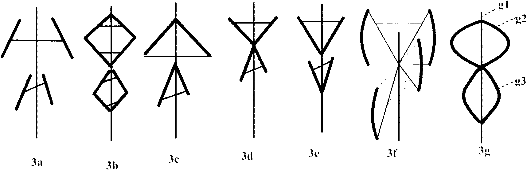
[0047] Example 3 adopts a triangular-supported string wind rotor composed of two H-shaped 2-blade single wind rotors.

[0048] as attached Figure 7 shown. In the picture:

[0049] 71 is the blade of the upper single wind rotor, 72 is the oblique support arm, 73 is the central axis of the wind rotor, 74 is the horizontal beam, 75 is the horizontal support arm, 76 is the blade of the lower single wind rotor, 77 is the horizontal support arm, 78 is a horizontal beam, and 79 is a generator.

[0050] Its oblique arm 72 is connected with horizontal crossbeam 74, adopts horizontal arms 75, 77 to support at the intersection of upper floor wind wheel and lower floor wind wheel, 75 and 77 form a cross shape, and they are in the same horizontal plane altogether.


PUM


Abstract

The invention relates to a method for constructing a string-type wind wheels and a corresponding magnetic levitation string-type windmill. Two or more Darrieus-type wind wheels with two to three blades respectively are connected in series and mounted in the vertical direction to form a new wind wheel which has the characteristics and the key points for generating the self-starting capability: (1) an included angle theta of the connecting lines between the geometric center points of the cross sections of any two adjacent blades and the rotating center of the wind wheels in the whole projection of the wind wheels in the vertical direction meets the following conditions that: the sum of all acute angles theta is larger than 120 degrees, and preferably, theta=360 / sigma y, wherein y is the blade number of wind wheels; (2) the axial crossed part of the blades of the upper layer and the lower layer is not larger than 25 percent of the height sum of the wind wheels of the upper layer and the lower layer; (3) the maximum diameter difference of the wind wheels of all the layers is not larger than 1 / 3; and (4) the height difference of the wind wheels of all the layers is not larger than 50 percent. The string-type wind wheels are constructed according to the conditions, and the magnetic levitation string-type windmill is constructed by further adopting the magnetic levitation technology so that the string-type windmill can be started more easily start and has high efficiency.

Description

technical field [0001] The invention relates to a string type wind wheel and a construction method of a magnetic levitation string type windmill, belonging to the energy field of wind kinetic energy utilization. Background technique [0002] The interception of wind energy to drive wind turbines mainly depends on the wind rotor, and the form of the wind rotor is not only closely related to the utilization rate of wind energy, but also closely related to the cost of wind energy utilization. The Darrieus type wind rotor is a vertical-axis lift type wind rotor, which has the characteristics of no need to align the wind direction, quiet operation, and easy manufacture. Therefore, it is also one of the main types of wind rotors currently used for wind power generation, and it has been continuously improved. Various structures, it has many deformations, including Φ type, H type, △ type, ◇ type and S type in the configuration of the wind rotor, straight blades, C-shaped curved blad...

Claims


Application Information

Patent Timeline
Patent Type & Authority Applications(China)
IPC IPC(8): F03D3/02F16C32/04H02N15/00F03D9/00
CPCY02E10/72Y02E10/74
Inventor 李永平
Owner 李永平
Why Eureka
Try Eureka