Gas and solid separator of recirculating fluidized bed boiler and boiler containing same

A technology of gas-solid separator and circulating fluidized bed, which is applied in the direction of fluidized bed combustion equipment, separation method, dispersed particle separation, etc., can solve the problems of large amount of fly ash, high concentration of smoke and dust emission, high power consumption of induced draft fan, etc. Achieve the effects of improving overall energy efficiency, reducing smoke and dust emissions, and simplifying manufacturing and installation

Inactive Publication Date: 2011-05-18
王森
View PDF5 Cites 9 Cited by
  • Summary
  • Abstract
  • Description
  • Claims
  • Application Information

AI Technical Summary

Problems solved by technology

[0004] At present, the circulating fluidized bed separator with the highest share in the international and domestic markets is the cyclone separator. Its typical structure is a high-temperature cyclone separator made of refractory materials. Its main advantage is high separation efficiency, and its main disadvantage is its bulky size. , The tangential inlet of the separator has high wind speed and large resistance, high power consumption of the induced draft fan, gas-solid two-phase flow in the opposite direction of the silo air flow, and the high-speed air flow entrains a large amount of fly ash, and the original emission concentration of smoke and dust is high. The separator needs to be lined It is insulated from the external thermal insulation, and the use of wear-resistant and high-temperature resistant materials consumes a large amount, which not only increases the cost of raw materials and manufacturing and installation of the separator, but also has a large thermal inertia, which is easy to coke at high temperature, and the boiler starts and stops slowly.
Some boilers use water-cooled or steam-cooled cyclone separators. Although the wear-resistant and high-temperature resistant materials are reduced, the problem of large thermal inertia is solved, the boiler does not coke, and the start and stop are fast, but there are also high wind speeds, large resistance, and induced draft fans. The power consumption is high, and the separation efficiency and stability are lower than those of high-temperature cyclone separators. In addition, its manufacturing process is complicated, resulting in high prices and low market share.
[0005] Although the gas-solid separation in the circulating fluidized bed boiler disclosed in the invention patent with the application number 200910308160.1 has many advantages compared with the popular circulating fluidized bed boiler gas-solid separation in the market, such as low flow resistance and saving induced draft fan power The membrane water wall structure saves high temperature and wear-resistant materials, etc., but there are still many defects in its structure, such as the entrance and exit of the turning channel are unimpeded, one is the poor inertial separation performance of the gas-solid two-phase after the entrance and exit It affects the inertial separation efficiency. Second, the diffusion area of ​​the gas-solid two-phase entering the turning channel is small, which affects the gravity settlement efficiency. Third, there is no water-cooled wall on the front and rear walls of the silo. The non-heated surface steel structure not only affects the quality life of the furnace wall but also increases the non-heated surface. Surface steel consumption is not conducive to anti-coking; Fourth, the application range of this structure is small, and it is more suitable for circulating fluidized bed and fluidized bed boilers with low magnification, which is not conducive to the development of large-scale

Method used


Image

  • Gas and solid separator of recirculating fluidized bed boiler and boiler containing same
  • Gas and solid separator of recirculating fluidized bed boiler and boiler containing same
  • Gas and solid separator of recirculating fluidized bed boiler and boiler containing same

Examples


Embodiment 1

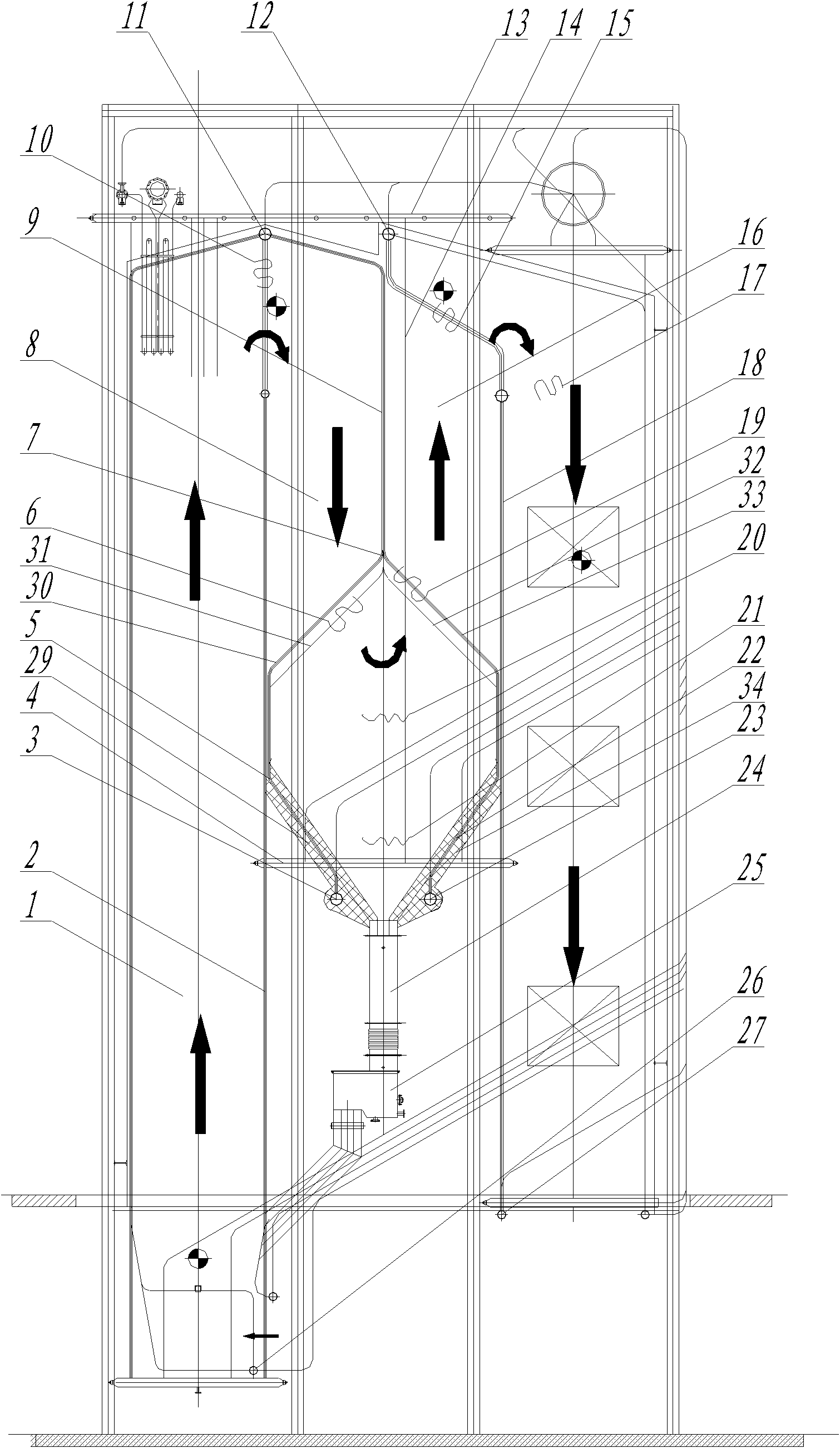
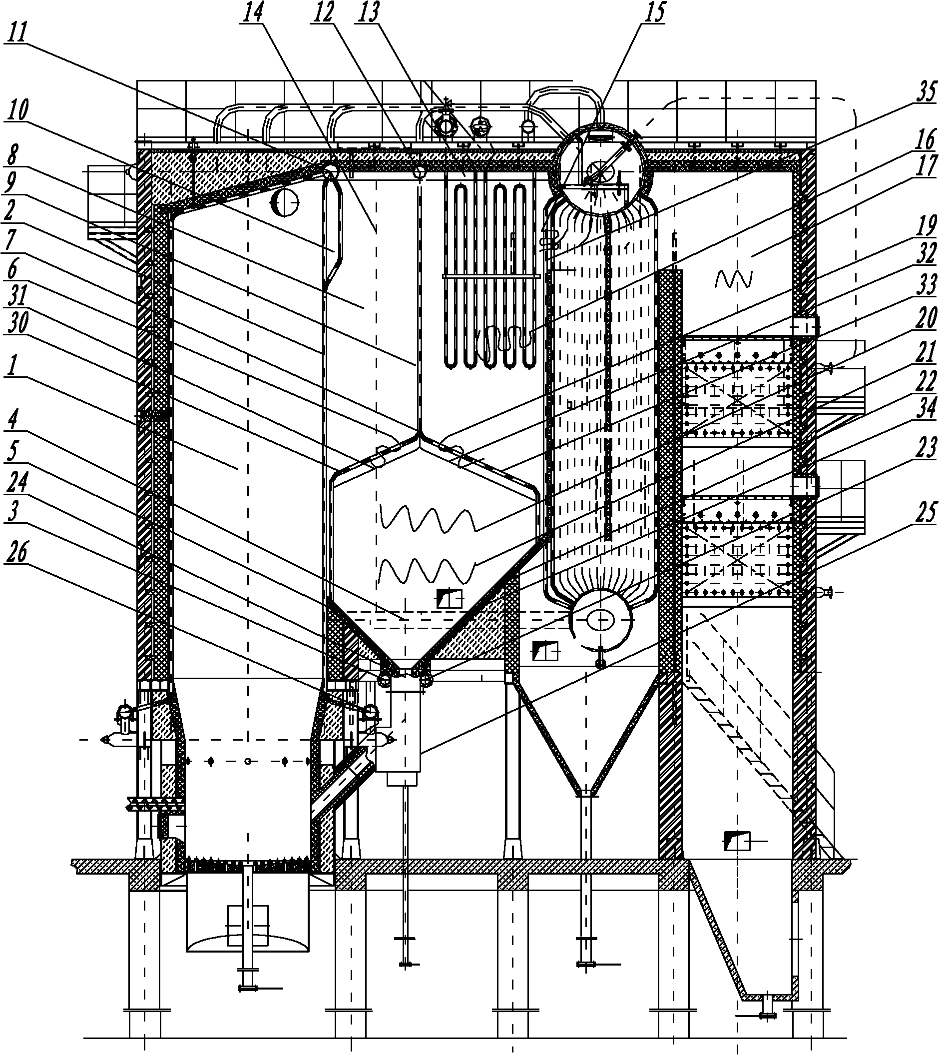
[0028] see figure 1 with figure 2 A gas-solid separator for a circulating fluidized bed boiler is characterized in that the flue gas inlet and outlet of the turning channel 20 form a flow-balanced separation tube bundle that is beneficial to the flow-balanced collision inertial separation of smoke and dust. The gas-solid separator is arranged at the rear of the furnace 1, and includes a downgoing flue 8 and an upgoing flue 16 separated from front to back by the lower and upper turning membrane screen 9 leading to the flue gas. exist figure 1 Among them, the lower and upper folding membrane screen 9 for guiding the flue gas is in the middle or in front of the rear wall 2 of the furnace and the front wall 18 of the shaft flue. figure 2 Among them, the lower and upper folding membrane screen 9 for guiding the flue gas is in the middle or front of the rear wall 2 of the furnace and the front row of convection tube bundles 35. figure 1 Among them, the upper end of the lower an...

Embodiment 2

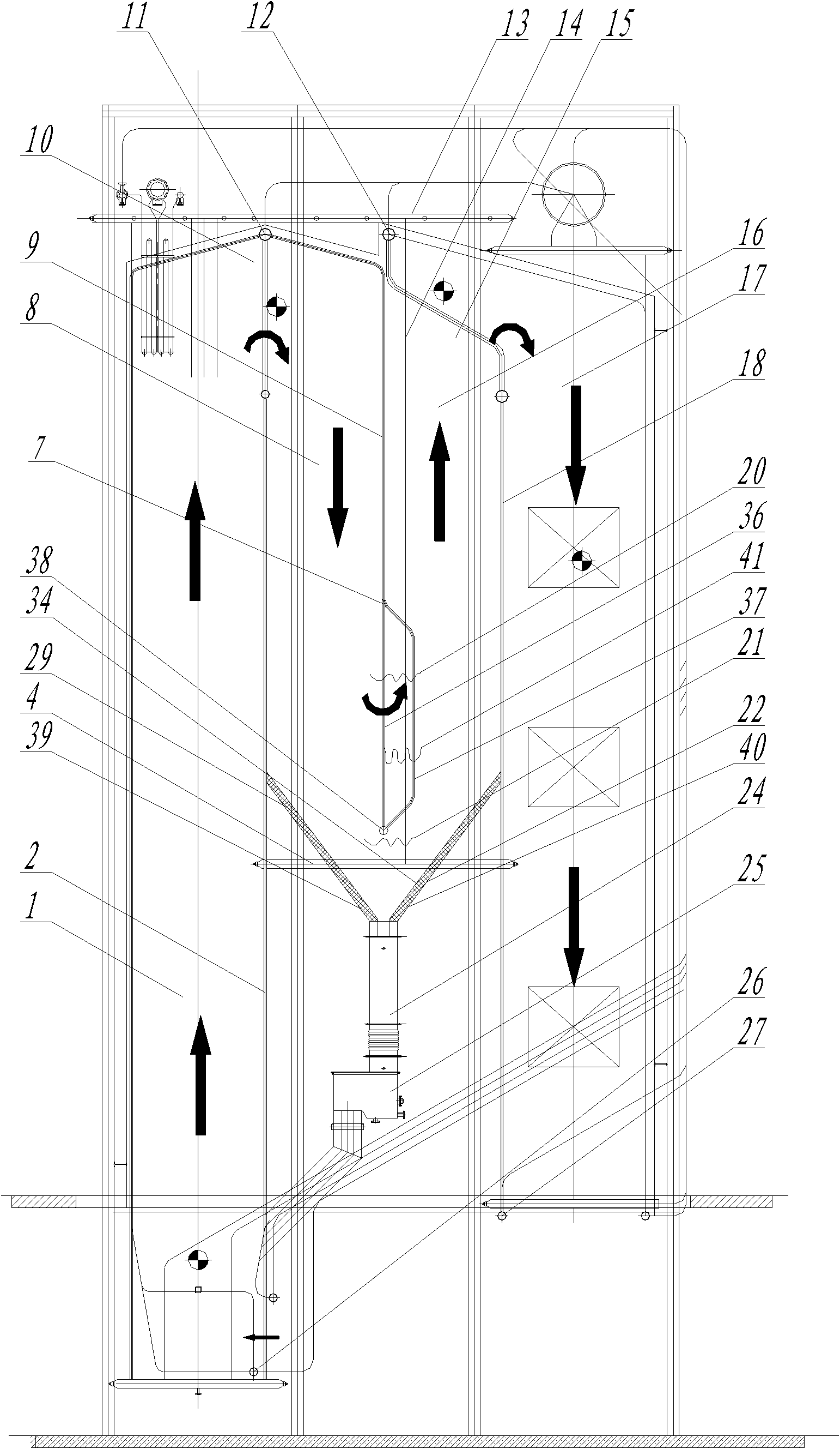
[0034] see image 3 with Figure 4 , and the difference from Embodiment 1 is that two rows of tube bundles 36, 37 are formed on the turning channel at the lower part of the bifurcation 7 of the membrane screen. The specific structure is: the lower part of the membrane-type screen bifurcation 7 divides two rows of tube bundles with loose spacing, the lower end of the front row of tube bundles 36 communicates with the center of the upper part of the lower horizontal header 38 of the tube bundles, and the rear row of tube bundles 37 is a distance away from the front row of tube bundles 36. Its lower end communicates radially with the rear wall of the lower horizontal header 38 of the tube bundle. The front row of tube bundles 36 and the rear row of tube bundles 37 constitute the flow-equalizing and separating tube bundles on the turning channel. The upper end of the feed bin front wall supporting plate 39 is closely sealed with the furnace rear wall, and its lower end is closel...

Embodiment 3

[0039] see Figure 5 , and the difference from Embodiment 1 is that: the lower end of the upper and lower folding membrane screen 9 leading to the flue gas is provided with a horizontal header 43 under the membrane screen connected to it, and the lower and upper folding membrane screen 9 of the guiding smoke passes through The transverse header 43 under the membrane screen communicates with the front outer tube bundle 30 , the front inner tube bundle 31 , the rear inner tube bundle 32 and the rear outer tube bundle 33 .


PUM


Abstract

The invention discloses a gas and solid separator of a recirculating fluidized bed boiler, which comprises a downstream flue and an upstream flue which are partitioned by a guiding flue gas up-down replicating film type screen, wherein the downstream flue and the upstream flue are communicated with storage bins hermetically installed below the downstream flue and the upstream flue through a turning channel, the front upper part of the gas and solid separator is provided with a flue gas inlet, the back upper part of the gas and solid separator is provided with a flue gas outlet, and four walls of the gas and solid separator are all heated water-cooling walls integrated with the boiler; and the gas and solid separator also comprises a uniform flow separating pipe bundle positioned on the turning channel, the upper end of the uniform flow separating pipe bundle on the turning channel is communicated with the guiding flue gas up-down replicating film type screen, and the lower end of the uniform flow separating pipe bundle on the turning channel is communicated with a lower transverse container. The invention also discloses a recirculating fluidized bed boiler containing two sets of gas and solid separators. The recirculating fluidized bed boiler has the advantages of wide application range, advanced process, simple manufacturing and installation, energy saving, consumption reduction and obvious emission reduction.

Description

technical field [0001] The invention relates to a gas-solid separator, the core component of a circulating fluidized bed boiler, and a boiler containing the gas-solid separator. , The large expansion turning channel and the silo are the inertial gravity separator that is naturally formed by the heating surface space integrated with the boiler body. In particular, it involves the new product design of the gas-solid separator for circulating fluidized bed boilers and the energy saving and emission reduction transformation of various circulating fluidized bed boilers and layer fired chain boilers. Background technique [0002] Circulating fluidized bed boiler combustion technology is widely recognized as a "clean" combustion technology with the most development prospects due to its advantages such as wide fuel adaptability, high combustion efficiency, low nitrogen oxide emissions, high-efficiency desulfurization, and good load regulation performance. [0003] The circulating f...

Claims


Application Information

Patent Timeline
Patent Type & Authority Applications(China)
IPC IPC(8): F23C10/18B01D45/00
CPCF23J2900/15025F23J2217/20B01D45/12F23C10/10F23J15/022
Inventor 王森
Owner 王森
Why Eureka
Try Eureka