Energy coupling device suitable for rectangular-crossed double-gate slow-wave structure

A technology of slow-wave structure and energy coupling, which is applied in the direction of the coupling device of the transit time type electron tube, etc., and can solve problems such as failure to work, poor performance of input and output devices, and limited operating bandwidth.

Inactive Publication Date: 2011-05-18
UNIV OF ELECTRONIC SCI & TECH OF CHINA
View PDF4 Cites 35 Cited by
  • Summary
  • Abstract
  • Description
  • Claims
  • Application Information

AI Technical Summary

Problems solved by technology

Young-Min Shin et al. proposed a rectangular interleaved double-grid slow-wave structure and then designed a supporting input and output device (the plan view is as follows: figure 2 shown), but the performance of this input and output devi

Method used


Image

  • Energy coupling device suitable for rectangular-crossed double-gate slow-wave structure
  • Energy coupling device suitable for rectangular-crossed double-gate slow-wave structure
  • Energy coupling device suitable for rectangular-crossed double-gate slow-wave structure

Examples


Embodiment Construction

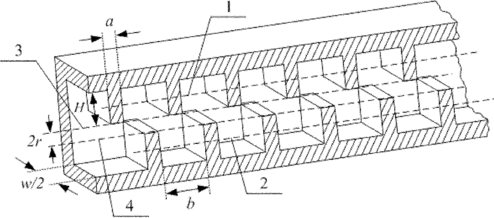
[0021] An energy coupling device suitable for a rectangular staggered double-grid slow-wave structure, its longitudinal half-section structure is as follows Figure 4 As shown, the corresponding two-dimensional plane diagram is shown as Figure 5 As shown, the connection end with the rectangular waveguide transitions to the other end connected with the rectangular interleaved double-grid slow-wave structure. The part connected to the rectangular waveguide is a rectangular waveguide whose wide side length is w and the narrow side length is k; Wave structure composition. Define the plane where the upper electric field surface (the upper waveguide wide surface) of the rectangular waveguide with the length of the wide side w and the length of the narrow side k is located as the upper reference plane 1, and define the lower electric field surface of the rectangular waveguide with the length of the wide side w and the length of the narrow side k The plane where the (lower waveguid...


PUM


Abstract

The invention relates to an energy coupling device suitable for a rectangular-crossed double-gate slow-wave structure, belonging to the technical field of vacuum electronics. One end of the device is connected with a rectangular waveguide, and the other end is connected with a rectangular-crossed double-gate slow-wave structure; the part connected with the rectangular-crossed double-gate slow-wave structure comprises an upper row and a lower row of rectangular gate waveguide structures which are mutually staggered and distributed and have gradually changed height; the half-height positions of the rectangular gates at the upper row are in an upper datum plane (1); all half-height positions of the rectangular gates at the lower row are in a lower datum plane (2); counted from a port connected with the rectangular-crossed double-gate slow-wave structure, the heights of the upper row and the lower row of rectangular gates are gradually reduced to zero; and the maximum height of the rectangular gates does not exceed the rectangular gate height of the rectangular-crossed double-gate slow-wave structure. The invention has the advantages of favorably coupling a microwave signal into the rectangular-crossed double-gate slow-wave structure, favorably extracting the amplified microwave signal from the rectangular-crossed double-gate slow-wave structure and being easy to connect with a traditional standard waveguide device.

Description

technical field [0001] The invention belongs to the technical field of vacuum electronics, in particular to an input-output structure in a rectangular interlaced grid traveling wave tube. Background technique [0002] Traveling wave tube is the most important type of microwave source in the field of vacuum electronics technology. It has the characteristics of high power, high efficiency, high gain, broadband and long life. It is widely used in radar, guidance, satellite communication, microwave remote sensing, and radiation measurement. And other fields, its performance directly determines the level of equipment. The core component of a traveling wave tube is a slow wave structure. Commonly used slow-wave structures include helix, coupling cavity, and meander waveguide. The output power of these structures working in the submillimeter wave and terahertz wave bands is limited, and the structure processing is very difficult. [0003] In order to meet the needs of practical a...

Claims


Application Information

Patent Timeline
IPC IPC(8): H01J23/42
Inventor 赖剑强宫玉彬许雄魏彦玉段兆云岳玲娜王文祥
Owner UNIV OF ELECTRONIC SCI & TECH OF CHINA
Why Eureka
Try Eureka