Diode pumping slab fixed laser

A solid-state laser and diode technology, applied in semiconductor lasers, lasers, semiconductor laser excitation devices, etc., can solve the problems of pump surface pollution, complex device structure, reduced device efficiency and lifespan, etc., and achieves low and high sealing requirements. Laser output, the effect of reducing the complexity of the structure

Inactive Publication Date: 2011-05-18
BEIJING INSTITUTE OF TECHNOLOGYGY
View PDF1 Cites 10 Cited by
  • Summary
  • Abstract
  • Description
  • Claims
  • Application Information

AI Technical Summary

Problems solved by technology

This not only makes the structure of the device complex, but also easily causes contamination of t

Method used


Image

  • Diode pumping slab fixed laser
  • Diode pumping slab fixed laser
  • Diode pumping slab fixed laser

Examples


Embodiment 1

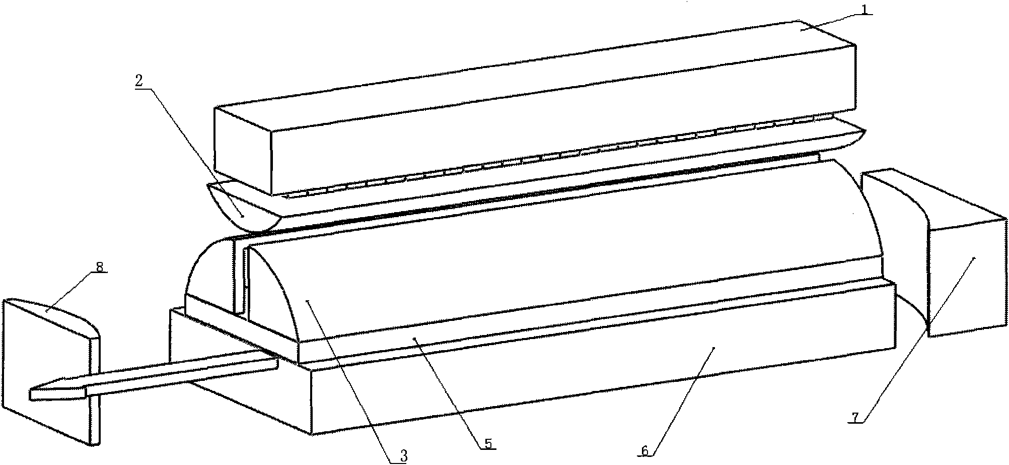
[0030] refer to figure 1 As shown in FIG. 4 , the diode-pumped slab solid-state laser includes a gain block, an input mirror 7 and an output mirror 8 . The gain module includes a diode array 1 composed of multiple laser diodes, a focusing mirror 2 , a condenser cover 3 , a slab-shaped gain medium 5 and a heat sink 6 . A set of opposite side surfaces of the slab-shaped gain medium 5 are polished and coated with an anti-reflection coating for the oscillating laser or the amplified light, serving as a light-transmitting surface for the laser or the amplified light. The lower surface of the slat-shaped gain medium 5 is gold-plated and sealed with the heat sink 6. The condenser cover 3 is placed on the upper surface of the slat-shaped gain medium 5, as shown in FIG. The pump light enters the gain medium again after being reflected by the condenser, which improves the utilization rate of the pump light and prevents the laser diode from being damaged due to the unabsorbed pump light...

Embodiment 2

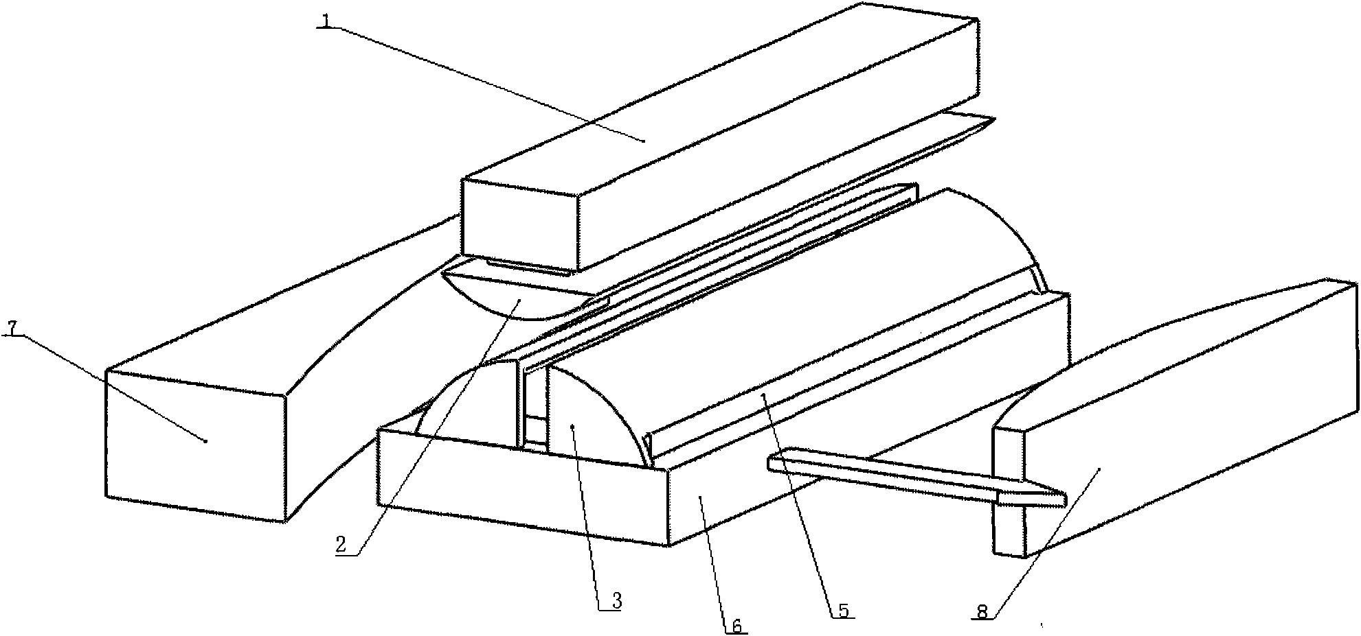
[0033] refer to figure 2 , the connection relationship of other structures is the same as in Embodiment 1, the condenser cover 3 is covered outside the slab-shaped gain medium 5 and placed on the heat sink 6, and the slab-shaped gain medium 5 at the lower end of the condenser cover 3 is coated with an anti-reflection film The position processing has a light outlet.

Embodiment 3

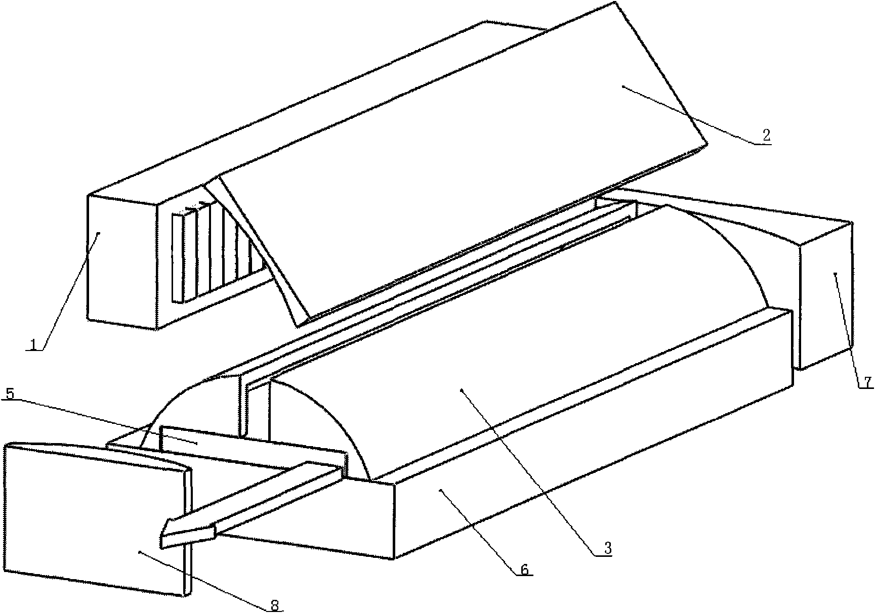
[0035] As shown in reference 3, the connection relationship of other structures is the same as that in Embodiment 1, and the focusing mirror 2 is a concave cylindrical reflector; A light outlet is processed at the position where the anti-reflection film is coated on the slat-shaped gain medium 5 at the lower end.

[0036] Taking the connection relationship of Embodiment 2 as an example, different slab-shaped gain media 5, input mirror 7 and output mirror 8 are selected to form a laser oscillator or laser amplifier of a diode-pumped slab solid-state laser to verify its oscillation or amplification. Effect.

[0037] The slab-shaped gain medium 5 adopts a laser crystal with a size of 50mm×200mm×1.5mm; the input mirror 7 adopts a concave spherical mirror with a radius of curvature of 600mm, and the structure is as follows Image 6 As shown; the output mirror 8 is a convex cylindrical mirror with a radius of curvature of -400mm; it forms a diode-pumped positive branch mixed cavity...


PUM

PropertyMeasurementUnit
Thicknessaaaaaaaaaa
Widthaaaaaaaaaa
Lengthaaaaaaaaaa

Abstract

The invention relates to a diode pumping slab fixed laser comprising a gain module, an input mirror and an output mirror. The gain module comprises a focusing mirror, a focusing hood, a slab-shaped gain medium, a heat sink and a diode array comparing a plurality of diodes, wherein the focusing hood is provided with a light inlet at the upper end and hoods a large surface of the slab-shaped gain medium, the other large surface of the slab-shaped gain medium is tightly connected with the heat sink, a pair of opposite sides of the slab-shaped gain medium is polished and coated with a reflection-reducing coating to be used as a light-transmitting surface of vibrating light or amplified light, the input mirror and the output mirror are respectively arranged at both sides of the gain module, and two sides of the slab-shaped gain medium, which are coated with the reflection-reducing coating, are opposite to form a resonance cavity. The diode pumping slab fixed laser has a simple structure, can realize the laser output with high power and high beam quality, and can be favorably applied to occasions with lower output power requirements.

Description

technical field [0001] The invention relates to a diode-pumped slab solid-state laser, which belongs to the field of solid-state lasers. Background technique [0002] Slab laser is an important way to obtain high power and high beam quality laser output. According to different pumping methods, slab lasers are divided into three structures: end-pumped, side-pumped, and large-area-pumped. In view of the geometrical characteristics of the slab-shaped gain medium (thickness is much smaller than the dimensions of the other two directions), using two larger surfaces as cooling surfaces can obtain a good cooling effect, and can efficiently transfer waste heat to achieve high-power laser output. In order to realize the separation of the light-passing surface and the cooling surface, the end-face or side pumping method is often used. However, the area of ​​the end face and side is small, which is not conducive to the injection of high pump light power. At the same time, due to the...

Claims


Application Information

Patent Timeline
IPC IPC(8): H01S5/22H01S5/04H01S5/024H01S5/026
Inventor 张恒利崔丽徐浏辛建国
Owner BEIJING INSTITUTE OF TECHNOLOGYGY
Why Eureka
Try Eureka