
Fault protection device of high-energy power supply system and protection method thereof

A power system and fault protection technology, applied in emergency protection circuit devices, emergency protection circuit devices for limiting overcurrent/overvoltage, circuit devices, etc. The problem of secondary damage and the inability to reduce the manufacturing cost, so as to achieve the effect of fast and reliable protection function, good economy and lower production cost.

Active Publication Date: 2014-08-06
GLORYMV ELECTRONICS
View PDF2 Cites 0 Cited by
  • Summary
  • Abstract
  • Description
  • Claims
  • Application Information

AI Technical Summary

Problems solved by technology

In the case of multiple capacitors with high energy storage density connected in parallel, once an internal short-circuit fault occurs in one of the capacitors, the energy stored in the remaining capacitors will all be poured into the short-circuit capacitor, and the capacitor will explode in this fault state. Consequences, will also cause secondary damage to the power supply system due to the explosion. In the prior art, in the application of multi-capacitor parallel connection, a current-limiting element with a certain resistance and inductance is connected in series to each parallel capacitor to achieve In the event of a single capacitor short-circuit fault state, it is used for current-limiting protection purposes, but the current-limiting element needs to absorb the high energy storage energy of multiple capacitors without explosion. The weight and volume of a single current-limiting element must be large, and Each capacitor needs to be equipped with a current-limiting element capable of withstanding large power capacity, resulting in the size and weight of the entire power supply assembly cannot be reduced, and the manufacturing cost cannot be reduced

Method used


Image

  • Fault protection device of high-energy power supply system and protection method thereof

Examples


Embodiment Construction

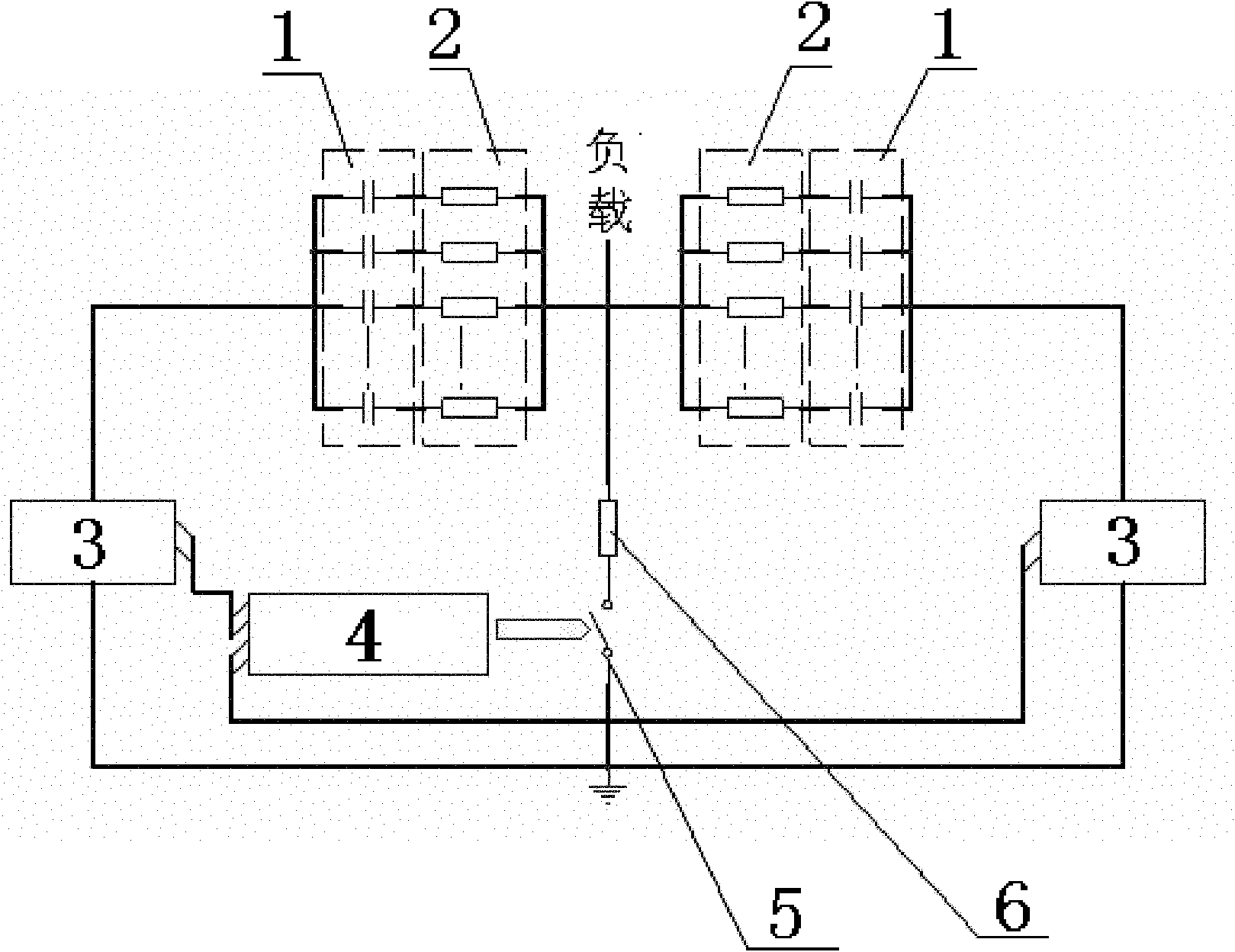
[0018] Such as figure 1 As shown, in the present invention, the high voltage ends of two groups of energy storage capacitor groups 1 are connected in parallel with the controllable switch 5 and the energy absorbing resistor 6 to connect to the load after being connected in series with the current limiting element group 2 respectively; The voltage terminals are respectively connected in series with a current detection unit 3, so that the energy storage capacitor bank 1 is detected in real time through each set of current detection units 3, and the opening and closing of the controllable switch 5 is controlled, and the energy absorbing resistor 6 is connected to the fault when a fault occurs. The energy storage capacitor bank 1 performs energy release.

[0019] The drive control unit 4 is connected in series between the two current detection units 3; the drive control unit 4 drives the opening and closing of the controllable switch 5, so that when the current detection unit 3 de...


PUM


Abstract

The invention discloses a protection method for a fault protection device of a high-energy power supply system. The fault protection device is characterized in that high-voltage ends of two groups of energy storage capacitor banks are respectively connected with a current-limiting element group in series and then connected with a controllable switch and an energy absorption resistor in parallel to be connected to a load; and low-voltage ends of the two groups of energy storage capacitor banks are respectively connected with one current detecting unit in series. By adopting the structure and the method, the fault protection device and the protection method thereof have the advantages of capabilities of reducing the size and the production cost of a high-energy power supply system by replacing a high-grade current limiting element with a small-size low-grade current limiting element, rapid and reliable protection function, wide applicability and favorable economy, simple structure and suitability for large-scale production and reformation.

Description

technical field [0001] The invention relates to a high-energy power supply system, in particular to a protection method for a fault protection device of a high-energy power supply system. Background technique [0002] The exploration and research of new energy has always been the research direction of the country's cutting-edge science and technology. With the continuous development of the country's science and technology and economy, the research requirements for new energy research devices have also been raised. The power system part of this type of research device is currently Usually, multiple capacitors are connected in parallel, so that the energy storage capacity can reach several megajoules to hundreds of megajoules, meeting the demand for high energy storage. [0003] The life of high-density energy storage capacitors has always been a key issue in research, especially in the process of fast charging and discharging, its life will be greatly shortened. In the case ...

Claims


Application Information

Patent Timeline
Patent Type & Authority Patents(China)
IPC IPC(8): H02H9/02
Inventor 王年峰宫龙刘林
Owner GLORYMV ELECTRONICS
Learn More