This helps you quickly interpret patents by identifying the three key elements:
Problems solved by technology
Method used
Benefits of technology
Problems solved by technology
That is, in this type of bearing, the reduction of the resistance when the lubricant passes and the reduction of the amount of oil film sheared during the ball movement cannot be achieved at the same time
Therefore, at present, even if a concave portion is formed on the inner diameter surface of the dimple, torque reduction cannot be achieved
[0015] In addition, if the surface roughness of the contact surface is reduced to reduce the sealing torque as in the bearing with seal in Patent Document 3, the torque reduction effect is limited.
If a non-contact seal is used, although the sealing torque can be made zero, reducing the sealing gap to the extent that can prevent the intrusion of foreign matter such as the above-mentioned gear wearpowder will cause problems due to assembly errors, processing errors, and thermal expansion differences. etc., so it is difficult to achieve
Method used
Image
Click on the blue label to locate the original text in one second.
Reading with bidirectional positioning of images and text.
Examples
Embodiment 1
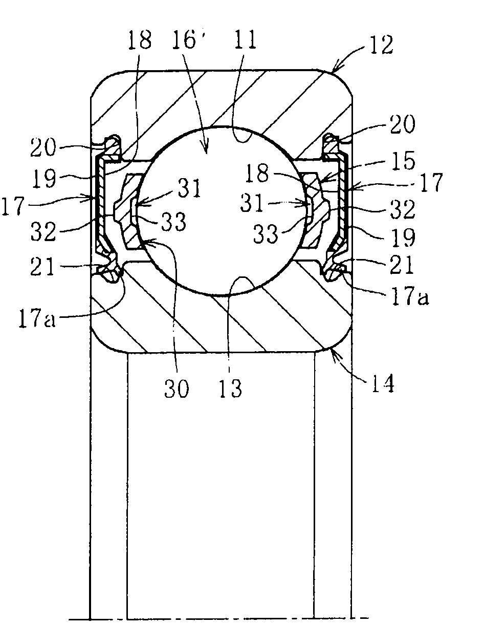
[0101] Make cages of shapes A, B, C, D, E, and F shown in Fig. 4 (metal cages: stamped products), and assemble them figure 1 ball bearing shown, and measure the resulting torque. The results are shown in Table 1 below. In Table 1, the standard product is a conventional product in which the ball non-contact portion 31 is not formed.
[0104] *1 Object after shifting the position of shape A from the P.C.D to the outer diameter side by 0.8mm
[0105] *2 The object after shifting the position of shape B from the P.C.D to the outer diameter side by 0.8mm...
Embodiment 2
[0110] Such as Figure 9 As shown, make a cage (metal cage: stamped product) with a slit 35, and use it to assemble Figure 8 For the ball bearing shown, the resulting torque was measured. At this time, the contact area is reduced by 30% compared to the standard part (holder without slit 35). As in Example 1, a rotational speed of 4000 r / min was applied with a radial load of 500 N applied. A part was immersed in lubricating oil (Toyota Genuine ATF T-4) at 30°C. At this time, the rotational torque is reduced by about 40%. That is, the standard is 0.152 Nm, and the cage having the slit 35 is 0.093 Nm. In addition, as the bearing, the outer diameter of the outer ring 12 is 72.0 mm, the inner diameter of the outer ring 12 is 60.2 mm, the outer diameter of the inner ring 14 is 47.0 mm, the inner diameter of the inner ring 14 is 35.0 mm, ball (steel Ball) 16 has an outer diameter of 11.1 mm. In addition, components of the same size were also used in Comparative Examples 1 and ...
Embodiment 3
[0116] FIG. 14 is a graph showing test results obtained by comparing the rotational torque of the bearing with seal according to this embodiment with that of a conventional bearing with seal. Such as Figure 14A As shown, the rotational torque in the bearing with a seal according to the embodiment is significantly reduced compared with the conventional product. The reason is that, if Figure 14B As shown, in the conventional products, as the main cause of the rotational torque, the resistance caused by the grease, (cage shear resistance + rolling resistance) and the sealing torque can be mentioned specifically. On the other hand, the embodiment Sealing torque in sealed bearings was ruled out as the main cause.
PUM
Abstract
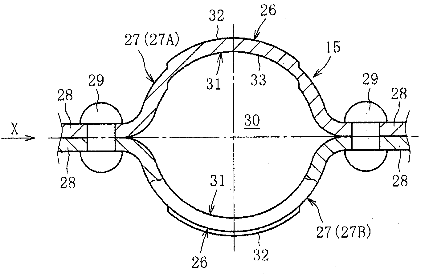
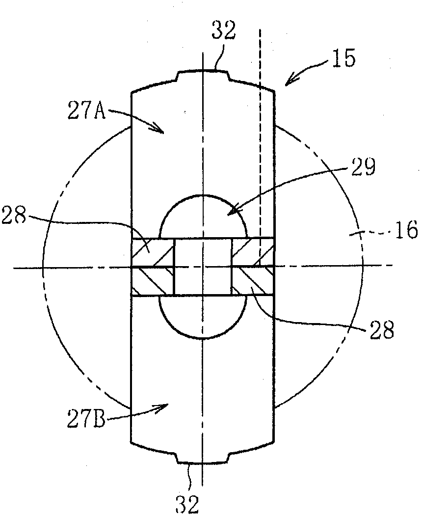
Provided are a retainer achieving low torque, a deep groove ball bearing using the retainer, and a bearing equipped with a seal, capable of preventing entry of foreign matter into the bearing and having sufficiently reduced seal torque. The retainer is formed by combining two annular holding plates (27A, 27B) each having hemispherical protrusions (26) circumferentially arranged at predetermined intervals. Pockets (30) for retaining balls (16) are formed by opposed hemispherical protrusions (26, 26). Contactless sections (31) with which a ball (16) does not make contact are formed on those surfaces of each pocket (30) which face the ball. The area of contact of each pocket (30) with the ball (16) is set less by 15% to 30% than the area of contact of the pocket (30) with the ball (16) when the contactless sections (31) are not provided. A seal member (17) is a contact seal in which a seal lip (17a) makes contact with the other raceway ring. The material of at least the front end of the seal lip (17a) is an easily wearable high wear material.
Description
technical field [0001] The invention relates to a cage, a deep groove ball bearing and a bearing with a seal. Background technique [0002] Such as Figure 15 As shown, the bearing (deep groove ball) has: an outer ring 2 with an arc-shaped outer raceway surface 1 formed on the inner periphery; an arc-shaped inner raceway surface 3 opposite to the outer raceway surface 1 is formed on the outer periphery The inner ring 4; the retainer 5 arranged between the inner ring 4 and the outer ring 2; a plurality of balls Bo supported by the retainer 5 for free rolling. [0003] Such as Figure 16 As shown, the retainer 5 is formed by combining two annular retaining plates 7 and 7 having hemispherical bulging portions 6 arranged at predetermined intervals along the circumferential direction. That is, each annular holding plate 7 is constituted by the hemispherical bulging portions 6 arranged along the circumferential direction and the flat portion 8 between adjacent hemispherical bulg...
Claims
Application Information
Patent Timeline
Application Date:The date an application was filed.
Publication Date:The date a patent or application was officially published.
First Publication Date:The earliest publication date of a patent with the same application number.
Issue Date:Publication date of the patent grant document.
PCT Entry Date:The Entry date of PCT National Phase.
Estimated Expiry Date:The statutory expiry date of a patent right according to the Patent Law, and it is the longest term of protection that the patent right can achieve without the termination of the patent right due to other reasons(Term extension factor has been taken into account ).
Invalid Date:Actual expiry date is based on effective date or publication date of legal transaction data of invalid patent.

