Heat exchanger and air conditioner having the heat exchanger

A heat exchanger and air flow technology, applied in heat exchange equipment, fixed heat exchangers, indirect heat exchangers, etc., can solve the problems of increased heat transfer rate, increased pressure loss, increased cost, etc., to achieve thermal Increased interchangeability, good assembling properties, and good adhesion

Active Publication Date: 2011-05-18
MITSUBISHI ELECTRIC CORP
View PDF2 Cites 12 Cited by
  • Summary
  • Abstract
  • Description
  • Claims
  • Application Information

AI Technical Summary

Problems solved by technology

However, by reducing the size and diameter of the heat transfer tube, the heat transfer rate in the tube increases, and the pressure loss increases accordingly. Therefore, it is necessary to optimize these elements
In addition, the miniaturized and thinner heat transfer tube is advantageous in terms of heat transfer performance, but since the production of the heat transfer tube or the attachment of the heat transfer tube and the plate fin is performed by welding, there are costs such as assembly. increase the problem

Method used


Image

  • Heat exchanger and air conditioner having the heat exchanger
  • Heat exchanger and air conditioner having the heat exchanger
  • Heat exchanger and air conditioner having the heat exchanger

Examples


Embodiment approach 1

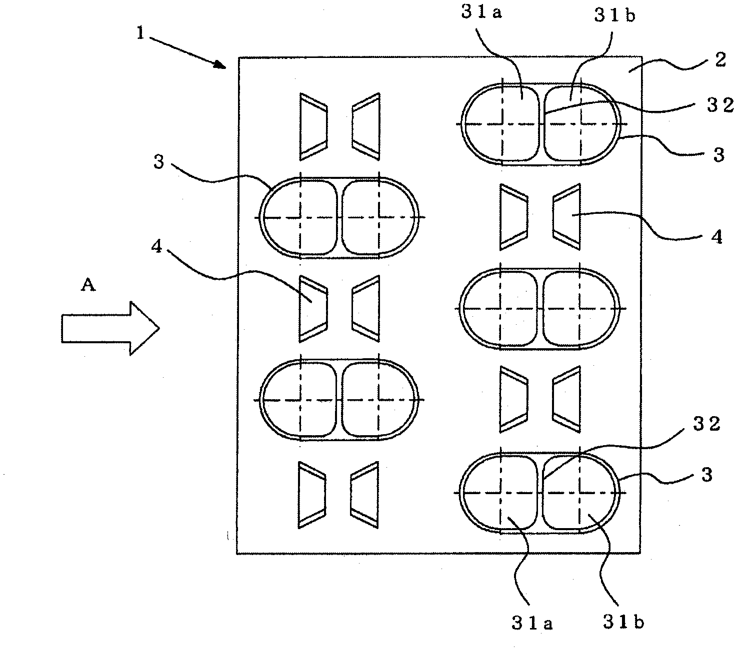
[0025] figure 1 It is a front view showing the outline of the heat exchanger according to Embodiment 1 of the present invention. exist figure 1 Among them, 1 is a heat exchanger, including: a plurality of plate-shaped fins 2 arranged at predetermined intervals; inserted in the direction perpendicular to the plate-shaped fins 2, through which the pipe is expanded (also called diameter expansion) ) and a plurality of flat-shaped heat transfer tubes 3 joined to the plate fins 2 . The plate-shaped fins 2 are made of metal plates such as copper or copper alloys, or aluminum or aluminum alloys (the same applies to other embodiments), and are parallel to the air flow direction A and at predetermined intervals in the vertical direction (depth direction) of the drawing. Arrange settings. Further, on the plate-shaped fins 2 , flat-shaped heat transfer tubes 3 , which will be described later, are provided in a plurality of stages and in one row or more in a direction perpendicular t...

Embodiment approach 2

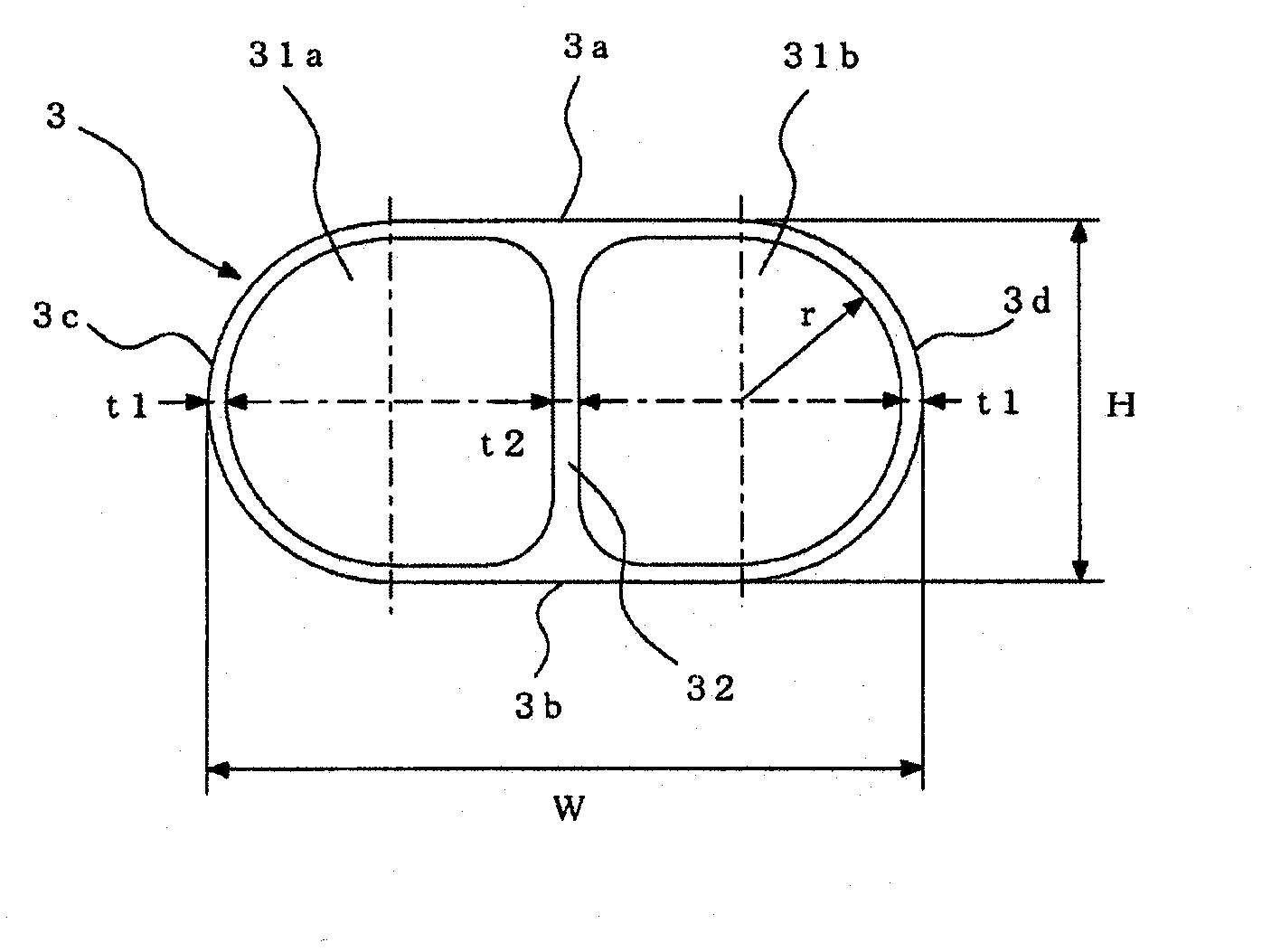
[0033] Figure 5 It is a front view showing the flat heat transfer tube of Embodiment 2. The heat transfer tube 3 of this embodiment and figure 2 In the same way as in the case of FIG. 1 , first and second refrigerant passages 31a and 31b constituted by through holes having a substantially D-shaped cross section are provided on both sides in the width direction. In addition, on the inner wall surfaces of the first and second refrigerant passages 31a, 31b, there are provided in the axial direction at predetermined heights and intervals, respectively, with substantially quadrangular cross-section (the front end is formed in a shape with some roundness). a plurality of protrusions 33 .

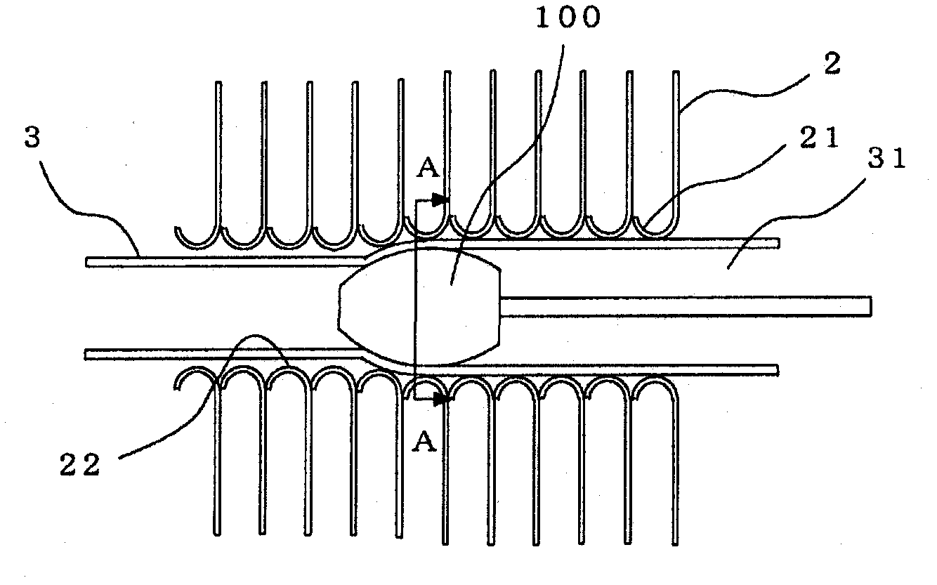
[0034]Such a flat-shaped heat transfer tube 3 is inserted into the mounting hole 22 of the plate-shaped fin 2 according to the above-mentioned point, and the pipe expander scraper ball 100 with the same cross-sectional shape (approximately D-shaped) as the above is used to pass through each pr...

Embodiment approach 3

[0037] Figure 7 It is a front view showing the flat heat transfer tube of Embodiment 3. The heat transfer tube 3 of this embodiment and figure 2 In the same way as in the case of FIG. 1 , first and second refrigerant passages 31a and 31b constituted by through holes having a substantially D-shaped cross section are provided on both sides in the width direction. In addition, on the inner wall surfaces of the first and second refrigerant passages 31a and 31b, a plurality of refrigerant passages having a substantially quadrilateral cross section (with some roundness at the front ends) are provided in the axial direction at predetermined heights and intervals. Protruding strips 33,34. The protruding strips 34 are arranged at the corners of the partition wall 32, and then set to the front ends of the protruding strips 33, 34 and the circle of the radius R according to the required height h, that is, the circular outer peripheral surface of the expander scraper ball 100 (refer t...


PUM


Abstract

Provided are a heat exchanger and an air conditioner equipped with the heat exchanger. The heat exchanger has enhanced heat exchange ability and reduced airflow resistance. These are achieved by using heat transfer tubes which are not deformed by the pressure therein despite the heat transfer tubes having a flat shape, which make very close contact with plate-like fins, and which are mounted easily. The heat exchanger is provided with plate-like fins (2) arranged at predetermined intervals, and also with flat heat transfer tubes (3) passed through the plate-like fins (2) in the direction perpendicular to the plate-like fins (2) and allowing a refrigerant to flow in the heat transfer tubes (3). Each heat transfer tube (3) has an outer shape having flat outer surfaces arranged along the direction of airflow and having a substantially oval cross-sectional shape. Inside each heat transfer tube (3) are formed first and second refrigerant flow paths (31a, 31b) which are two symmetrical substantially D-shaped through-holes arranged with a partition wall (32) provided between the first and second refrigerant flow paths (31a, 31b). The first and second refrigerant flow paths (31a, 31b) areexpanded in diameter by means of a pipe expanding billet ball to join each heat transfer tube (3) to the plate-like fins (2).

Description

technical field [0001] The present invention relates to a heat exchanger and an air conditioner including the heat exchanger. Background technique [0002] Among conventional heat exchangers constituting an air conditioner, there is a type called a finned tube heat exchanger. This heat exchanger is composed of plate-shaped fins arranged at regular intervals, through which gas (air) flows, and flat heat transfer tubes inserted perpendicular to the plate-shaped fins, through which refrigerant flows. As a configuration, a plurality of ridges are provided in the axial direction on the inner surface of the heat transfer tube (for example, refer to Patent Document 1). In addition, there is a type in which the flat heat transfer tube has a porous structure, or a type in which a plurality of slits formed by cutting are provided on the plate-like fins. In addition, the slit group is arranged so that the side ends of the slits face the air flow direction, and the velocity boundary l...

Claims


Application Information

Patent Timeline
Patent Type & Authority Applications(China)
IPC IPC(8): F28F1/32F25B1/00F25B39/00F28D1/047F28F1/02F28F1/40
CPCF28F2275/125F28F1/40F28F1/325F28D1/0478F28F1/022Y10T29/49373F28F1/405F28F1/10B21D53/08F25B1/005F28F1/12
Inventor 李相武石桥晃松田拓也
Owner MITSUBISHI ELECTRIC CORP
Why Eureka
Try Eureka